
INTRODUCTION
This TEK describes procedures for determining loads to be used when designing masonry buildings to resist earthquakes. The information provided herein is an overview of methods for determining the design ground motion, calculating the building base shear and distributing earthquake forces to lateral load resisting elements. Also reviewed are the earthquake forces on masonry walls when they are loaded out-of-plane.
With the merging of the model building codes used in various regions of the United States into the International Building Code (IBC, ref. 1), the trend in structural design is to refer to nationally approved standards for various aspects of design. The 2003 IBC references Minimum Design Loads for Buildings and Other Structures, ASCE 7-02 (ref. 2) for determining design loads, including earthquake loads, on structures. This TEK does not address the seismic design of non-building masonry structures. TEK 14-18B (ref. 3) covers prescriptive seismic reinforcement requirements for masonry structures.
LOAD DETERMINATION
Determination of Design Ground Motion
The first step in obtaining the seismic design forces on masonry buildings is to determine the maximum earthquake intensity that the building must be designed to resist. Since the risk of earthquakes occurring and the intensity of ground shaking that may take place varies over the United States, the seismic design force varies with the building location. ASCE 7 addresses this issue by defining a design earthquake for all regions in the United States. The design earthquake is two thirds of the maximum considered earthquake, which is the ground motion that causes the most severe effects considered by the code. In most parts of the United States, the maximum considered earthquake corresponds to a ground motion with a 2 percent chance of being exceeded in fifty years. While more intense ground shaking may occur in these regions, it is generally considered uneconomical to design for such uncommon earthquakes. In regions of high seismicity, however, such as California, the maximum considered earthquake is based on the characteristic magnitudes of earthquakes on known active faults. Since these faults can produce characteristic earthquakes every few hundred years, the ground motion corresponding to a 2 percent chance of being exceeded in 50 years will be significantly larger than the ground motion and structural periods corresponding to large magnitude earthquakes on known faults. Therefore, the maximum considered earthquake in regions of high seismicity is typically a deterministic ground motion based on the known characteristics of nearby faults.
For design purposes, ASCE 7 represents earthquake intensity by means of acceleration response spectra, as shown in Figure 1. Modeling of the ground motion in this manner provides structure-dependent information on the ground motion because buildings respond differently depending on their dynamic characteristics. ASCE 7 contains maps that provide spectral response acceleration values for the maximum considered earthquake ground motion for short period (0.2- second), Ss, and long period (1-second), S1, responses for the entire United States. The design earthquake, in turn, corresponds to two-thirds of the maximum considered earthquake. The spectral response values used for design are then given by:

The site class coefficients, Fa and Fv, depend on the soil properties at the site. ASCE 7 identifies six site classes (A through F) based on soil properties. The mapped spectral are given for Site Class B and modifications must be made to obtain the values for other site classes. Site classification is typically determined by a professional geotechnical engineer at the beginning of a project. However, if the soil properties are not known in sufficient detail to determine the site class, Class D may be used if approved by the building official. Figure 1 shows how the design response spectrum is obtained from the spectral response parameters.

Seismic Base Shear
The seismic base shear is the total design lateral force at the base of a building. The base shear is calculated using the design ground motion described in the previous section and modified to account for the structural characteristics and importance placed on a building.
ASCE 7 provides several structural analysis methods for calculating the seismic base shear. This TEK discusses the equivalent lateral force procedure, which is the most commonly used technique for seismic analyses. The equivalent lateral force procedure is a linear static analysis technique that approximates nonlinear building response by use of the response modification factor R, which accounts for a building’s inherent ductility and overstrength. ASCE 7 permits the use of the equivalent lateral force procedure for the design of most buildings, except for those with certain irregularities and buildings with periods greater than 3.5 seconds, such as high-rise buildings. ASCE 7 Table 9.5.2.2 provides values of R for various masonry structural systems. The seismic base shear is given by the following equation:

but need not be greater than

The occupancy importance factor, I, is used to ensure that larger forces are used to design buildings for which the consequences of failure may be more severe.
Equations 3 and 4 represent the base shear obtained from the design response spectrum shown in Figure 1, divided by the response modification factor. In addition to these equations, ASCE 7 also stipulates that the design base shear should not be less than:

or, for buildings and structures in Seismic Design Categories E and F, less than:

Vertical Distribution of Seismic Base Shear
When performing equivalent lateral force analysis, the earthquake load is distributed vertically over the height of the building by applying a portion of the seismic base shear to each level of the building, consistent with the assumption of concentrated floor masses. The force at each level, Fx is given by:

where: k = 1 for T ≤ 0.5 seconds; k = 2 for T ≥ 2.5 seconds. Linear interpolation is used for determining k between 1 and 2 for 0.5 < T < 2.5.
Horizontal Distribution of Seismic Base Shear
Once the seismic force at each floor has been determined from Equation 7, the story shear must be distributed to the lateral load resisting elements at each story. This varies depending on whether the diaphragm is rigid or flexible when compared to the stiffness of the lateral load resisting element. Masonry elements are typically quite stiff and conventional practice is to assume that wood floors and roofs or steel decks without concrete topping are flexible diaphragms. Conversely, concrete and hollow core slabs or steel decks with concrete topping are considered rigid diaphragms.
Figure 2 shows the difference in response of buildings with flexible diaphragms and buildings with rigid diaphragms. With flexible diaphragms, the force is distributed in proportion to the tributary area supported by each wall, whereas the rigid diaphragms distribute the force in proportion to wall stiffness.

Earthquake Loads on Components and Connections
When masonry walls are loaded out-of-plane they act as elements of the structure, or components, that resist the earthquake loads generated by their self-weight. For satisfactory structural response, the wall must span between supports and transfer lateral loads to the floor or roof diaphragm, which in turn transfers the loads to the lateral load resisting system.
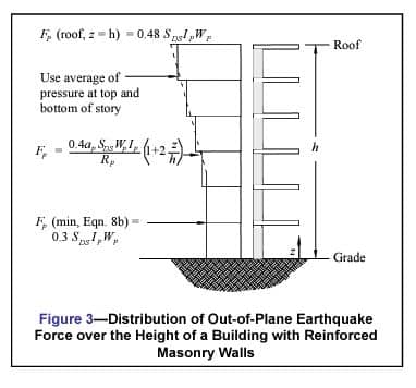
Out-of-plane earthquake loads on masonry walls and their connections are calculated using the requirements of ASCE 7 for components. The following equation is used to determine the seismic design force Fp on the wall, which is distributed relative to the wall mass distribution:

The seismic force need not exceed

and should not be less than

Figure 3 shows the distribution of earthquake forces over the height of a building when calculated using Equation 8. Since the wall is supported at the bottom and top of each story, the average of the forces calculated for the floor above and the floor below is used to design walls in each story. This ensures that the earthquake forces are applied in proportion to the mass distribution of the wall.
Since earthquake ground motion is cyclic, walls should be evaluated for the out-of-plane demands in both directions to determine the most critical condition. The most severe condition usually occurs when the earthquake loads are applied outward since the eccentricity of the gravity loads from a roof or floor adds to the earthquake induced-moment. In addition, walls should be evaluated for all applicable load combinations in ASCE 7, including load combinations in which the vertical component of the ground motion is negative. This combination usually results in the smallest axial load on a wall and is important to consider since wall capacity and response can be dependent on axial load.
EXAMPLE
Calculate the following earthquake loads on the two-story building constructed with special reinforced masonry shear walls shown in Figure 4:
- earthquake load on the seismic force resisting system, and
- out-of-plane earthquake load on a typical second story wall.
The building is located at a site with Ss = 1.2g and S1 = 0.4g (SDC D). The building’s occupancy importance factor and component importance factor are equal to 1.0. The site classification for the project is D.
Solution a) earthquake load on the seismic force resisting system
- Seismic Weight
The portion of the total gravity load of the structure located at the roof and second story is:
wroof = 356 kip (1,584 kN)
w2 = 571 kip (2,540 kN)
The effective seismic weight of the building includes the total dead load plus any other code-prescribed loads. The total effective seismic weight, W, is:
W = 356 + 571 = 927 kip (4,124 kN) - Fundamental Period of Vibration
In lieu of calculating the building period using a computer analysis, ASCE 7 permits the use of an approximate fundamental period using the following equation:
Ta = Cthny
The parameters Ct and y are equal to 0.02 and 0.75, respectively, for masonry buildings. Thus,

- Seismic Base Shear
From ASCE 7 Tables 9.4.1.2.4a and Table 9.4.1.2.4b, Fa =1.02, Fv =1.6. Therefore,
SDS = ⅔Fa</sub> Ss = 2/3(1.02)(1.2) = 0.82g
SD1 = ⅔Fv S1 = 2/3(1.6)(0.4) = 0.43gThe seismic base shear is equal to

but need not be greater than

The design base shear should not be less than:
V = 0.044SDSIW = 0.044(0.82)(1.0)(927) = 33 kip (147 kN)
- Vertical Distribution of Seismic Base Shear
The force at each level, Fx is given by:

Where k = 1.0 since T = 0.26 seconds, which is less than 0.5 seconds. Table 1 provides the vertical distribution of base shear to the floors of the building. Figure 5 shows the story shear and overturning moment at each floor of the building. At the second story, the steel deck is assumed to act as a flexible diaphragm and the story shear will be distributed to each wall based on the tributary area it supports. The second floor diaphragm with concrete topping is assumed to act as a rigid diaphragm and distributes the earthquake load to the walls in proportion to their stiffness. The engineer should confirm these assumptions by comparing the in-plane deflection of the diaphragms to the lateral displacement of the walls.
Solution b) out-of-plane earthquake load on a typical second story wall
From Equation 8, the out-of-plane seismic pressure attachment at the wall attachment point at the second floor is equal to:

which is less than the maximum pressure of:

and greater than the minimum pressure which is given by:

The pressure at the roof is equal to:

Since the earthquake pressure should be distributed uniformly over the height of the wall in proportion to the wall distribution of mass, the uniformly distributed earthquake pressure in the wall for the second story is equal to:

For the first story, the pressure at the wall attachment point at the ground level is:

Because this is less than the minimum pressure of 21 psf (1,005 Pa) from Equation 8b, use an average of 21 psf (1,005 Pa) at the ground level and 22 psf (1,053 Pa) previously calculated for the attachment point at the second level:
Fp = (21 + 22)/2 = 22 psf (1,053 Pa)
Figure 6 shows the out-of-plane earthquake forces on the masonry walls. Note that the load on the unbraced parapet is calculated using an amplification factor, ap of 2.5.


NOTATIONS
ap amplification factor that represents the dynamic p amplification of the wall relative to the fundamental period of the structure. For most masonry walls, ap = 1.0, except for parapets and unbraced walls for which ap = 2.5.
Ct building period coefficient
Cvx vertical distribution factor
Fa acceleration-based site class modification factor at short periods (0.2 second)
Fv velocity-based site class modification factor at long periods (1-second)
Fp seismic design force on the wall, psf (kPa)
Fx force at each level, kip (kN)
h average roof height of structure with respect to the base, ft (m)
hi height from the base to level i, ft (m)
hn height from the base to the highest level of the structure, ft (m)
hx height from the base to level x , ft (m)
I occupancy importance factor
Ip component importance factor that varies from 1.0 to 1.5
k an exponent related to the structure period: k = 1 for T ≤ 0.5 sec; k = 2 for T ≥ 2.5 sec; use linear interpolation to determine k for 0.5 < T < 2.5
N number of stories in a structure
R response modification factor per ASCE 7 Table 9.5.2.2
Rp response modification factor that represents the wall overstrength and ductility or energy absorbing capability. For reinforced masonry walls, Rp = 2.5 while for unreinforced masonry walls, Rp = 1.5.
Sa spectral response acceleration
Ss 5 percent damped, maximum considered earthquake spectral response acceleration at short periods (0.2- second)
S1 5 percent damped, maximum considered earthquake spectral response acceleration at long periods (1-second)
SDS 5 percent damped, design spectral response acceleration at short periods (0.2-second)
SD1 5 percent damped, design spectral response acceleration at long periods (1-second)
T fundamental period of the structure, sec
Ta approximate fundamental period of the structure, sec
V seismic base shear, kip (kN)
W effective seismic weight, kip (kN)
Wp wall weight, psf (kPa)
wi portion of building effective seismic weight W located at or assigned to level i
wx portion of building effective seismic weight W located at or assigned to level x
y building period exponent
z height of point of wall attachment with respect to the base, ft (m)
REFERENCES
- International Code Council (ICC), 2003 International Building Code, International Code Council, Inc., 2002.
- Minimum Design Loads for Buildings and Other Structures, ASCE-7-02. American Society of Civil Engineers, 2002.
- Prescriptive Seismic Reinforcement Requirements for Masonry Structures, TEK 14-18B. Concrete Masonry & Hardscapes Association, 2003.