INTRODUCTION
Structural design of buildings requires a variety of structural loads to be accounted for: dead and live loads, those from wind, earthquake, lateral soil pressure, lateral fluid pressure, as well as forces induced by temperature movements, creep, shrinkage, and differential movements. Because any load can act simultaneously with another, the designer must consider how these various loads interact on the wall. For example, an axial load can offset tension due to lateral load, thereby increasing flexural capacity, and, if acting eccentrically, can also increase the moment on the wall. Building codes dictate which load combinations must be considered, and require that the structure be designed to resist the most severe load combination.
The design aids in this TEK cover combined axial compression or axial tension and flexure, as determined using the allowable stress design provisions of Building Code Requirements for Masonry Structures (ref. 1). The data in this TEK applies to 8 in. (203 mm) thick reinforced concrete masonry walls with a specified compressive strength, f’m, of 1500 psi (10.3 MPa), and a maximum wall height of 20 ft (6.1 m) (taller walls can be evaluated using the NCMA computer software (ref. 3) or other design tools). Reinforcing bars are assumed to be located at the center of the wall, and bar sizes 4, 5, 6, 7, and 8 are included.
AXIAL LOAD-BENDING MOMENT INTERACTION DIAGRAMS
Several design approaches are available for combined axial compression and flexure, most commonly using computer programs to perform the necessary iterative calculations, or using interaction diagrams to graphically determine required reinforcement for the given conditions. Axial load–bending moment interaction diagrams account for the interaction between moment and axial load on the design capacity of a reinforced (or unreinforced) masonry wall.
Regions of the Interaction Diagram
The various interaction diagram regions are discussed below. Figure 2 shows a typical interaction diagram for a reinforced masonry wall subjected to combined axial load and bending moment. Three distinct regions (I, II and III) can be identified, each with very different characteristics and behavior.
Region I represents the range of conditions corresponding to an uncracked section. That is, there is no tendency for the wall to go into tension, hence the design is governed by masonry compressive strength. Because the Building Code Requirements for Masonry Structures (ref. 1) only permits reinforcing steel to carry an allowable compression stress if it is laterally tied, and since it is generally not practical to do so, the reinforcing steel is simply neglected.
Region II is characterized by cracking in the section, but the reinforcing steel remains subject to compression strain. Hence in Region II, as in Region I, the reinforcing steel is ignored – i.e., the size and location of reinforcing steel are irrelevant. Since the section is cracked, the properties of the cross-section change as the eccentricity changes.
Region III corresponds to values of 0 ≤ k ≤ 1 (tension governs the design). This is the only region where the reinforcing steel affects the capacity of the section.
The load capacity can also be limited by wall slenderness if the eccentricity is sufficiently small and the slenderness sufficiently large. The horizontal line shown in Figure 2 in Region I illustrates the effect of this upper limit on the interaction diagram.
A complete discussion of interaction diagrams, including the governing equations for the various regions, is included in Concrete Masonry Design Tables (ref. 2).

Figures 3 Through 7
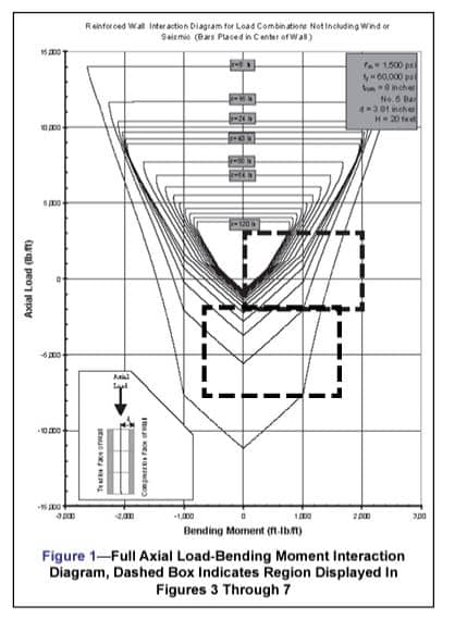
Figures 3 through 7 are axial load-bending moment interaction diagrams for reinforcing bar sizes No. 4, 5, 6, 7 and 8, respectively, which can be used to aid in the design of both fully and partially grouted 8 in. (203 mm) single wythe concrete masonry walls. Rather than the full interaction diagram, only the portion outlined by the dashed box in Figure 1 is shown. With reinforcing steel located in the center of the wall, wall strength will be the same under either a positive or negative moment of the same magnitude. Therefore, although negative moments are not shown, the figures may be used for these conditions.
This area of the interaction diagram covers the majority of design applications. Conditions outside of this area may be determined using Concrete Masonry Design Tables (ref. 2). Each line on the diagram represents a different reinforcing bar spacing, included at 8 in. (203 mm) increments.
Building Code Requirements for Masonry Structures (ref. 1) permits a ⅓ increase in allowable stresses when load combinations include wind or seismic loads. Figures 3 through 7 represent load combinations excluding wind or seismic (i.e., no increase in allowable stresses is included). However, these diagrams can be used for load combinations including wind or seismic by multiplying the total applied axial load and moment by 0.75 (see Design Example section).
These interaction diagrams also conform to the International Building Code (ref. 4) basic load combinations for allowable stress design (not including 1/3 stress increase for for wind or seismic). A stress increase is allowed under the IBC alternative basic load combinations but is applied in a different manner than in MSJC. Therefore, the IBC 1/3 stress increase cannot be used in conjunction with these tables.


DESIGN EXAMPLE – LOADBEARING WALL
A 20 ft (6.1 m) high reinforced concrete masonry wall is to be designed to resist wind load as well as eccentrically applied axial live and dead loads as depicted in Figure 8. The designer must determine the reinforcement size and spacing required to resist the applied loads, listed below.
D = 520 lb/ft (7.6 kN/m), at e = 0.75 in. (19 mm)
L = 250 lb/ft (3.6 kN/m), at e = 0.75 in. (19 mm)
W = 20 psf (1.0 kPa)
The maximum moment due to the wind load is determined as follows.

The axial load used for design is the axial load at the location of maximum moment. This combination may not necessarily be the most critical section for combined axial load and flexure, but should be close to the critical location. The wall weight is estimated to be halfway between fully grouted and hollow (82 and 38.7 psf (400 and 189 kg/m²), respectively, for 115 pcf (1842 kg/m³) unit concrete density).

The eccentricity of the axial loads also induces bending in the wall and should be included in the applied moment. The magnitude of the moment due to the eccentric axial load must be found at the same location as the maximum moment.

The induced bending moments due to the eccentric axial loads are insignificant compared to that due to wind. However, these will be taken into account where appropriate for specific load combinations.
The applicable load combinations (ref. 1) for this example are:
D + L
D + L + W
D + W
During design, all three load combinations should be checked, with the controlling load case used for design. For brevity, only the third combination (D + W) will be evaluated here, since the axial load actually increases the flexural capacity for the first two combinations by offsetting tension in the wall due to the lateral load. Because the interaction diagrams in this TEK are for load combinations excluding wind or seismic, the total moment, shear and axial loads the wall must resist (listed below) are multiplied by 0.75 to account for the ⅓ increase in allowable stresses permitted by section 2.1.1.1.3 in Building Code Requirements for Masonry Structures (ref. 1).


To determine the required reinforcement size and spacing to resist these loads, P10’ and Mmax are plotted on the appropriate interaction diagram(s) until a satisfactory design is found.
Figure 3 shows that No. 4 bars at 32 in. (813 mm) on center are adequate. If a larger bar spacing is desired, No. 5 bars at 48 in. (1219 mm) on center will also meet the design requirements (see Figure 4). Although wall design is seldom governed by out-of-plane shear, the shear capacity should be checked. In addition, the axial load should be recalculated based on the actual wall weight (based on grout spacing chosen), then the resulting required capacity should be recalculated and plotted on the interaction diagram to check adequacy.

NOMENCLATURE
An net cross sectional area of masonry, in.²/ft (mm²/m)
D dead load, lb/ft (kN/m)
d distance from extreme compression fiber to centroid of tension reinforcement, in. (mm)
e eccentricity of axial load – measured from centroid of masonry unit, in. (mm)
Fa allowable compressive stress due to axial load only, psi (MPa)
Fb allowable masonry compressive stress due to flexure only, psi (MPa)
Fs allowable steel tensile stress, psi (MPa)
fy yield stress of steel, psi (MPa)
f’m specified masonry compressive strength, psi (MPa)
H height of wall, ft (m)
k ratio of the distance between compression face of wall and neutral axis to the effective depth, d
L live load, lb/ft (kN/m)
M moment acting on section, in.-lb/ft or ft-lb/ft (kN m/m)
P axial force or concentrated load, lb/ft (kN/m)
Pb axial force corresponding to balanced condition, lb (kN)
Po maximum axial force ordinate on interaction diagram, lb (kN)
s reinforcement spacing, in. (mm)
t thickness of masonry, in. (mm)
tnom nominal wall thickness, in. (mm)
V shear acting at a section, lb/ft (kN/m)
W wind load, psf (kN/m²)
y distance measured from top of wall, ft (m)
METRIC CONVERSIONS
| To convert: | To metric units: | Multiply English units by: |
| ft | m | 0.3048 |
| ft-lb/ft | N m/m | 4.44822 |
| in. | mm | 25.4 |
| lb/ft | N/m | 14.5939 |
| psi | MPa | 0.00689476 |
REFERENCES
- Building Code Requirements for Masonry Structures, ACI 530/ASCE 5/TMS 402. Reported by the Masonry Standards Joint Committee, 1999/2002/2005.
- International Building Code. International Codes Council, Falls Church, VA, 2000/2003/2006.