INTRODUCTION
Standard joint reinforcement for concrete masonry is a factory fabricated welded wire assembly consisting of two or more longitudinal wires connected with cross wires forming a truss or ladder configuration. It was initially conceived primarily to control wall cracking associated with thermal or moisture shrinkage or expansion and as an alternative to masonry headers when tying masonry wythes together. Note that horizontal steel requirements for crack control can be met using joint reinforcement or reinforcing bars. See Crack Control Strategies for Concrete Masonry Construction, CMU TEC-009-23 (ref. 6).
Joint reinforcement also increases a wall’s resistance to horizontal bending, but is not widely recognized by the model building codes for structural purposes. In some instances, it may be used in design for flexural resistance or to meet prescriptive seismic requirements.
This TEK discusses the code and specification requirements for joint reinforcement and presents a general discussion of the function of joint reinforcement in concrete masonry walls. Detailed information on additional uses for joint reinforcement can be found in other TEK as referenced throughout this publication.
MATERIALS
Reinforcement types used in masonry principally are reinforcing bars and cold-drawn wire products. Joint reinforcement is governed by Standard Specification for Masonry Joint Reinforcement, ASTM A 951 (ref. 1), or Standard Specification for Stainless Steel Wire, ASTM A 580/580M Type 304 or Type 316 (ref. 2), if the joint reinforcement is stainless steel according to the Specification for Masonry Structures (ref. 3). Cold-drawn wire for joint reinforcement varies from W1.1 to W4.9 (11 gage to 1/4 in. diameter; MW7 to MW32), the most popular size being W1.7 (9 gage, MW11). Wire for masonry is plain, except side wires for joint reinforcement are deformed by means of knurling wheels.
Because Building Code Requirements for Masonry Structures (ref. 4) limits the size of joint reinforcement to one half the joint thickness, the practical limit for wire diameter is W2.8, (3/16 in., MW17) for a 3/8 in. (9.5 mm) bed joint. Joint reinforcement of this thickness may be difficult to install however, if a uniform mortar joint thickness of 3/8 in. (9.5 mm) is to be maintained.
Types of Joint Reinforcement
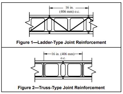
Reflecting its multiple purposes in masonry walls, joint reinforcement comes in several configurations. One longitudinal wire is generally required for each bed joint (i.e., two wires for a typical single wythe wall), but code or specification requirements may dictate otherwise. Typical joint reinforcement spacing is 16 in. (406 mm) on center. Adjustable ties, tabs, third wires and seismic clips are also available in combination with joint reinforcement for multi-wythe and veneer walls.
- Ladder-type joint reinforcement (Figure 1) consists of longitudinal wires flush welded with perpendicular cross wires, creating the appearance of a ladder. It is less rigid than truss type joint reinforcement and is recommended for multi-wythe walls with cavity spaces or unfilled collar joints. This permits the two wythes to move independently, yet still transfers outof-plane loads from the exterior masonry to the interior masonry wall. Cross wires 16 in. (406 mm) on center should be used for reinforced concrete masonry construction, to keep cross wires out of the core spaces, thus preventing them from interfering with the placement of vertical reinforcement and grout.
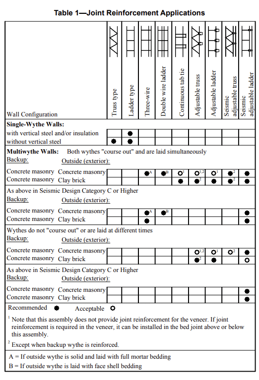
- Truss-type joint reinforcement (Figure 2) consists of longitudinal wires connected with diagonal cross wires. This shape is stiffer in the plane of the wall than ladder-type joint reinforcement and if used to connect multiple wythes restricts differential movement between the wythes. For this reason, it should be used only when differential movement is not a concern, as in single wythe concrete masonry walls. Because the diagonal cross wires may interfere with the placement of vertical reinforcing steel and grout, truss type joint reinforcement should not be used in reinforced or grouted walls.
- Tabs, ties, anchors, third wires and seismic clips of assorted configurations are often used with the joint reinforcement to produce a system that works to: control cracking; bond masonry wythes together; anchor masonry; and, in some cases, resist structural loads. Tie and anchor spacing and other requirements are included in Anchors and Ties for Masonry, TEK 12-01B (ref.5).
Recommendations for the use of some of the different types of joint reinforcement are listed in Table 1.
CORROSION PROTECTION
Grout, mortar and masonry units usually provide adequate protection for embedded reinforcement, provided that minimum cover and clearance requirements are met.
Coating Requirements
The carbon steel in joint reinforcement can be protected from corrosion by coating with zinc (galvanizing). The zinc protects steel in two ways. First, it provides a barrier between the steel and oxygen and water. Second, during the corrosion process, the zinc provides a sacrificial coating. The protective value of the zinc coating increases with increased coating thickness; therefore the required amount of galvanizing increases with the severity of exposure, as listed below (refs. 3, 4):
- Interior walls exposed to a mean relative humidity less than or equal to 75%:
Mill galvanized, ASTM A 641 (0.1oz/ft2)
(0.031 kg/m2)
Hot-dip galvanized, ASTM A 153 (1.5 oz/ft2)
(458 g/m2)
Stainless steel AISI Type 304 or Type 316
conforming to ASTM A 580
- Exterior walls or interior walls exposed to a
mean relative humidity > 75%:
Hot-dip galvanized, ASTM A 153 (1.5 oz/ft2 (0.46 kg/m2)
Epoxy coated, ASTM A 884 Class A Type 1, >
7 mils (175 mm)
Stainless steel AISI Type 304 or Type 316
conforming to ASTM A 580
Cover Requirements
Specification for Masonry Structures also lists minimum cover requirements for joint reinforcement as a further means of corrosion protection. It must be placed so that longitudinal wires are embedded in mortar with a minimum cover of:
- 1/2 in. (13 mm) when not exposed to weather or earth,
- 5/8 in. (16 mm) when exposed to weather or earth.
PRESCRIPTIVE CODE REQUIREMENTS
Building Code Requirements for Masonry Structures includes prescriptive requirements for joint reinforcement. There are multiple uses for joint reinforcement in masonry structures. Joint reinforcement can be used to provide crack control, horizontal reinforcement, and bond for multiple wythes, corners and intersections. The following list highlights only those requirements specific to joint reinforcement. Crack control topics are covered in CMU-TEC-009-23 (ref. 6). For information on anchors and ties, see Anchors and Ties for Masonry, TEK 12-01B (ref. 5). There is also a useful discussion on joint reinforcement as structural reinforcing in Steel Reinforcement for Concrete Masonry, TEK 12-04D (ref. 7).
General Requirements for Joint Reinforcement
- For masonry in other than running bond: Horizontal reinforcement shall be 0.00028 times the gross vertical cross-sectional area of the wall. This requirement can be met with joint reinforcement placed in the horizontal bed joints. For 8in. (203-mm) masonry walls, this amounts to W1.7 (9 gage, MW11) joint reinforcement every other course. There are additional criteria for stack bond masonry in Seismic Design Categories D, E and F.
- Seismic Requirements: In Seismic Design Category C and higher (for concrete masonry other than veneer), horizontal joint reinforcement spaced not more than 16 in. (406 mm) on center vertically with at least two wires of W1.7 (MW11) is required. Horizontal reinforcement also must be provided at the bottom and top of all wall openings and must extend at least 24 in. (610 mm) past the opening. Additional details on seismic requirements, including shear walls, are covered in Seismic Design and Detailing Requirements for Masonry Structures, CMHA TEK 14-18B (ref. 8).
Allowable Stress Design Requirements
- In addition to the requirements above, concrete masonry walls designed by the allowable stress method and bonded by wall ties must have a maximum tie spacing of 36 in. (914 mm) horizontally and 24 in. (610 mm) vertically. Joint reinforcement cross wires can be used in place of wall ties to meet this requirement.
- When the walls are designed for noncomposite action, truss-type joint reinforcing is not to be used for tying the wythes.
- Combination joint reinforcement with tabs or adjustable ties are popular options for bonding multiwythe walls and are governed by additional code requirements.
Empirical Design Requirements
- When two wythes of masonry are bonded with joint reinforcement, at least one cross wire must serve as a tie for each 22/3 ft2 (0.25 m2) of wall area. The vertical spacing of the joint reinforcement can not exceed 24 in. (610 mm), and the cross wires must be W1.7 (9 gage, MW11) minimum, without drips, and embedded in mortar.
- Intersecting walls, when depending on each other for lateral support, can be anchored by several prescriptive methods including the use of joint reinforcement spaced no more than 8 in. (203 mm) on center vertically. The longitudinal wires must extend at least 30 in. (762 mm) in each direction at the intersection and be at least W1.7 (9 gage, MW11).
- Interior nonloadbearing wall intersections may be anchored by several prescriptive methods, including joint reinforcement at a maximum spacing of 16 in. (406 mm) o.c. vertically.
Requirements for Use in Veneer
- Prescriptive requirements for joint reinforcement in masonry veneer are included in Building Code Requirements for Masonry Structures, Chapter 6. These provisions are limited to areas where the basic wind speed does not exceed 110 mph (177 km/hr) as listed in ASCE 7-02 (ref. 9). Additional limitations are covered in the Code. The information below is for joint reinforcement or the joint reinforcement portion of a tie/anchor system. For information on anchor and tie requirements see Concrete Masonry Veneers, TEK 03-06C (ref. 10).
- Ladder-type or tab-type joint reinforcement is permitted in veneer construction with the cross wires used to anchor the masonry veneer. Minimum longitudinal and cross wire size is W1.7 (9 gage, MW11), and maximum spacing is 16 in. (406 mm) on center vertically.
- Adjustable anchors combined with joint reinforcement may be used as anchorage with the longitudinal wire of the joint reinforcement being W1.7 (9 gage, MW11) minimum.
- Joint reinforcement may also be used to anchor masonry veneer to masonry provided the maximum distance between the inside face of the veneer and the outside face of the concrete masonry backup wythe is 4 1/2 in. (114 mm).
- In Seismic Design Categories E and F, the 2005 edition of Building Code Requirements for Masonry Structures requires continuous single wire joint reinforcement, W1.7 (9 gage, MW11) minimum, in the veneer wythe at a maximum spacing of 18 in. (457 mm) on center vertically. Clips or hooks must attach the wire to the joint reinforcement. The International Building Code 2003 (ref. 11) also mandates this requirement for Seismic Design Category D.
- Anchor spacings, and, as a result, possibly joint reinforcement spacing, are reduced for Seismic Design Categories D, E and F and in high wind areas.
Requirements for Use in Glass Unit Masonry
- Horizontal joint reinforcement is to be spaced no more than 16 in. (406 mm) on center, located in the mortar bed joint, and must not span across movement joints.
- Minimum splice length is 6 in. (152 mm).
- Joint reinforcement must be placed immediately above and below openings in the panel.
- Joint reinforcement must have at least 2 parallel, longitudinal wires of size W1.7 (9 gage, MW11) and have welded cross wires of W1.7 (9 gage, MW11) minimum.
INSTALLATION
Joint reinforcement installation is a routine task for masons. The joint reinforcement is placed on the face shells and mortar is placed over it. Cover requirements must be maintained. Installing the correct type of joint reinforcement with the specified corrosion resistant coating is important, as is making sure it is installed at the proper spacings and locations. Quality assurance provisions related to joint reinforcement generally include:
Submittals
Material Certificate indicating compliance should include:
- material meets specified ASTM standard,
- corrosion protection specified has been supplied,
- configuration specified has been supplied, and
- other criteria as required or specified.
Inspection
Oil, dirt and other materials detrimental to bond should be
removed. Light rust and mill scale are permissible.
- Cover requirements are met.
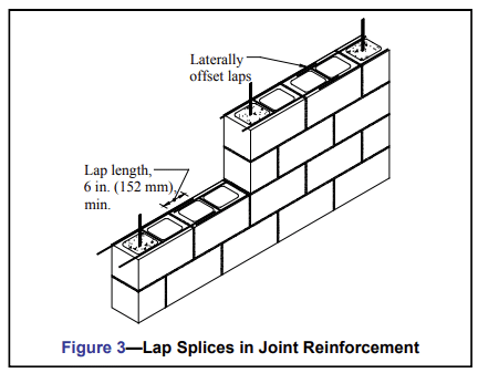
- Splices are a minimum of 6 in. (152 mm) (see Figure 3) to properly transfer tensile stresses. Tying is not necessary. Construction documents may specify longer splices, especially if the joint reinforcement is being used as part of the structural horizontal reinforcing steel.
- Verify that joint reinforcement utilized for crack control does not continue through movement joints.
- If ties or anchors are part of the joint reinforcement, check that embedment in the adjoining wythe, alignment and spacing are within specified values.
REFERENCES
- Standard Specification for Masonry Joint Reinforcement, ASTM A 951-02. ASTM International, 2002.
- Standard Specification for Stainless Steel Wire, ASTM A 580/580M-98(2004). ASTM International, 2004.
- Specification for Masonry Structures, ACI 530.1-05/ASCE 6 05/TMS 602-05. Reported by the Masonry Standards Joint Committee, 2005.
- Building Code Requirements for Masonry Structures, ACI 530 05/ASCE 5-05/TMS 402-05. Reported by the Masonry Standards Joint Committee, 2005.
- Anchors and Ties for Masonry, TEK 12-01B, Concrete Masonry & Hardscapes Association 2011.
- Crack Control Strategies for Concrete Masonry Construction, CMU-TEC-009-23, 2023.
- Steel Reinforcement for Concrete Masonry, TEK 12-04D, Concrete Masonry & Hardscapes Association, 2023.
- Seismic Design and Detailing Requirements for Masonry Structures, TEK 14-18B, Concrete Masonry & Hardscapes Association, 2003.
- Minimum Design Loads for Buildings and Other Structures, ASCE 7-02, American Society of Civil Engineers, 2002.
- Concrete Masonry Veneers, TEK 03-06C, Concrete Masonry & Hardscapes Association, 2012.
- International Building Code 2003. International Code Council, 2003.