INTRODUCTION
Condensation is one type of moisture to which buildings can potentially be exposed. In addition to above grade precipitates of rain, snow and ice as well as high humidity, several forms of below-grade ground-sourced moisture can also affect building envelopes. Concrete masonry walls are less affected by the problems associated with moisture infiltration and condensate than other building materials (i.e. corrosion, rotting, mold, delamination, blistering and volumetric changes). However, prolonged moisture accumulation can lead to reduced effectiveness of some types of thermal insulation, temporary frost formation and/or efflorescence. Fortunately, these problems can largely be avoided with proper wall design and construction.
Above- and below-grade condensation control strategies include: limiting air leakage and water vapor diffusion, using adequate amounts of thermal insulation, minimizing cold spots, utilizing free draining flashing and weeps, and allowing for drying. Because the condensation potential in a particular assembly can vary with the construction assembly, building type, building usage as well as environmental conditions and seasonal climate changes, however, these strategies may vary from project to project.
CONDENSATION
Warmer air can hold more water in vapor form than can cold air. When warm moist air comes into contact with a cold surface, the air cools and can no longer hold all of its water vapor—the excess moisture condenses.
Local cold spots in a wall can cause small areas of condensation. Cold spots are usually caused either by thermal bridging or by air leakage. Both can be avoided with appropriate design strategies. See TEKs 06-13B Thermal Bridges in Wall Construction and 06-14A Control of Air Leakage in Concrete Masonry Walls (refs. 1, 2) for more detailed information.
Restricting Water Vapor Flow
Water vapor can move through building envelope assemblies by diffusion and via air leakage, so both mechanisms must be considered. The amount of water vapor that travels via air movement can be several orders of magnitude greater than that due to diffusion. Therefore, limiting air leakage is an important water vapor control strategy. For detailed information on reducing air leakage, see TEK 06-14A. When an air barrier material is required, the vapor permeability of the material must be evaluated relative to the material’s location within the wall to help ensure that the air barrier material is not contributing to moisture problems due to vapor diffusion.
Proper design and construction to reduce liquid water entry into wall assemblies will also help reduce condensation potential by reducing moisture surface area and the related water vapor diffusion. The use of moisture tolerant building materials, such as concrete masonry, also reduces the potential damage from condensation and other moisture sources.
A balanced mechanical system backed by an appropriate maintenance program is assumed for optimum efficiency. Supplying draft-controlled make-up air for all exhaust fans reduces air infiltration.
When required, water vapor retarders are used to restrict water vapor diffusion (versus moisture movement due to air leakage). Although the main characteristic of water vapor retarders is vapor permeance, other considerations may include mechanical strength, adhesion, elasticity, thermal stability, fire and flammability resistance, resistance to other deteriorating elements (e.g., chemicals, UV radiation), and ease of application and joint sealing.
A vapor retarder’s effectiveness depends on both its vapor permeance and location within the wall assembly. In addition, because of the large potential for moisture movement with air movement, a vapor retarder in an assembly with high air leakage will be ineffective.
Vapor retarders can limit water vapor movement by diffusion, but can also limit the ability of the assembly to dry. Both results need to be considered in the design. In some cases, using a semi-permeable vapor retarder, or not using a vapor retarder, is recommended to ensure the wall assembly can adequately dry. Other design conditions may dictate the use of a vapor retarder of very low permeance. Each design should be evaluated with the goal of balancing the need to restrict vapor diffusion and the need to allow drying.
Materials are also available that serve as both the vapor retarder and airflow retarder, and are useful when the assessment of air flow control and vapor diffusion control so dictates.
The 2009 International Residential Code (ref. 8) defines three vapor control classes as follows:
- Class I: <0.1 perms, such as polyethylene sheet, sheet metal or aluminum facing.
- Class II: 0.1 – 1.0 perms, such as kraft faced fiberglass batts, and some vapor control paints.
- Class III: 1.0 – 10 perms, such as some latex or enamel paints.
CONDENSATION CONTROL
Condensation control focuses on minimizing airflow through the wall, interrupting water vapor diffusion, maintaining temperatures above the dew point for surfaces exposed to moisture, and allowing for drying.
Condensation can occur in either summer or winter. Design strategies for moisture control (including moisture vapor and humid air) under heating conditions often differ from those for cooling conditions, even though the basic principles of moisture transfer are the same.
In cold climates, moisture tends to be driven from the warm moist interior to the cold dry exterior. Condensation control under these conditions favors strategies that hold the moisture within the insulated envelope. In hot and humid climates, warm moist exterior air is driven towards the cooler drier interior. In this case, the wall should be designed to keep the moisture on the exterior of the wall. Most climates have some combination of the above conditions. In addition, moisture control in certain building types, such as hotels, motels, and cold storage facilities, will often benefit from using the recommendation for warm humid climates, regardless of the building location.
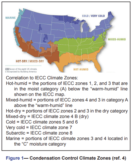
Definitions of climate zones for condensation control are based on the climate zones used in the International Energy Conservation Code (IECC) (ref. 3). The map showing these zones can be found at http://www1.eere.energy.gov/buildings/residential/ba_climate_guidance.html. Climate zones for the United States are: Sub-arctic, very cold, cold, mixed-humid, hot-humid, hot-dry, mixed-dry and marine. These zones are illustrated in Figure 1 for the continental U.S. along with their corresponding IECC climate zones.
Recommendations by Climate Zone
The following sections describe U. S. Department of Energy (DOE) general recommendations (ref. 5) for controlling water vapor movement and allowing drying in new residential construction, based on the climate zones shown in Figure 1.
All recommendations should be considered as part of a comprehensive strategy that addresses items including moisture management (including liquid and vapor, as well as drying potential), energy efficiency, air infiltration and durability.
All Climates
Some recommendations are consistent across all climates:
- An air space, such as the properly drained open cores of a single wythe masonry wall or the cavity in a masonry cavity wall, is recommended in all climate zones. The air space provides a drainage plane and allows for better drying. Single wythe masonry walls with completely filled grout spaces will take longer to dry than concrete masonry walls with unfilled cores or a cavity. However, these walls have a large hygroscopic moisture capacity and tend not to be damaged by the longer drying period.
- Impermeable interior coverings, such as vinyl wallpaper, are not recommended for exterior walls, because their non-breathable nature tends to trap moisture, inhibit drying and therefore can contribute to mold and mildew within such finishes.
- Interior polyethylene vapor retarders are generally not recommended, because they limit the wall’s ability to dry towards the inside. In some cases, these may be mandated by building codes, particularly in wet climates.
In this case, wall assemblies should be carefully designed to accommodate building materials, local climate conditions, and interior moisture loads.
An additional consideration applies to masonry veneers under certain summer conditions. If masonry is not treated for water repellency, water can be absorbed during heavy rains. Subsequent solar heating evaporates some water, raising the water vapor pressure of air in the wall, and potentially causing condensation. This can be prevented by using surface or integral water repellents to restrict wetting of the masonry, or by applying parging or sheathing paper on the exterior side of the insulation.
Cold and Very Cold Climates
Roughly the northern half of the United States experiences a heating dominated climate. Many areas also experience hot summers, however, so both seasons should be considered when designing for condensation control.
In cold and very cold climates, air barriers and vapor retarders are installed on the interior side of the insulation in building envelope assemblies when used. This approach allows the wall assembly to dry towards the exterior, as long as vaporpermeable exterior materials are used. For exterior masonry walls, drywall painted with latex paint (Class III) provides a sufficient vapor retarder.
Hot-Dry & Mixed-Dry Climates
Design considerations for the dry climates tend to focus less on water vapor control and more on issues such as intense solar radiation, brief heavy rains, and managing fire risk. Wall interiors can be painted but not covered with plastic vapor retarders or impervious coatings, such as vinyl wallpaper.
Hot and Humid Climates
Moisture is a significant problem in these climates in terms of both high humidity and high rainfall. Controlling the infiltration of this moisture-laden air into the building envelope and keeping moisture away from cold surfaces are the goals of design and construction in this climate zone.
Ideally in these climates, batt insulation, if used, should be unfaced. However, codes may restrict the use of unfaced batts in wall construction. In addition, because of the susceptibility of batt insulation to moisture, its use is not generally recommended in masonry wall assemblies. Though there are some exceptions, generally all wall interiors and finishes which are part of an insulated masonry wall assembly may be painted or otherwise finished if desired so long as such finishes and assemblies are breathable and permeable as Code and Standards allow. Masonry buildings in Florida have successfully used a non-breathable elastomeric paint on the exterior of the wall to serve as the vapor retarder.
In hot-humid climates the interior space should be dehumidified. Properly sized air-conditioning equipment will help reduce indoor humidity—oversized units should be avoided because they either cycle on and off too frequently or are off for too long a time to effectively dehumidify.
In humid climates, moisture may condense on wall exteriors, because the wall temperature can be below the ambient dew point. Areas such as shaded reentrant building corners are more difficult to dry, since they do not have the benefit of sun and wind for evaporation. In addition, extra care is required for building components prone to thermal bridging, such as walls adjacent to slab or floor edges as well as parapet courses adjacent to roof joists and decks (see Ref. 1 for information on control of thermal bridges).
Mixed-Humid Climates
The mixed-humid climate zone has generally moderate conditions, but can experience very cold winters and hot, humid summers. In these areas, wall assemblies need to be protected from getting wet from both the interior and exterior and should also be allowed to dry to either the exterior or interior.
Perhaps the least costly option is to allow water vapor to “flow through,” by using vapor-permeable building materials on both the interior and exterior. This allows water vapor to diffuse through the assembly from interior to exterior during heating periods and from exterior to interior during cooling periods. If a vapor retarder is used, a semi-permeable (i.e., Class III) vapor retarder on just the interior side is considered adequate. Although the DOE suggests latex paint as an adequate vapor retarder in these climates (ref. 5d), the permeability of latex paints varies with the specific paint and the number and thickness of coats. Consult the manufacturer for specific permeabilities.
Installing vapor retarders on both the interior and exterior to block moisture entry from both directions is not recommended, as any moisture that enters the wall is trapped.
Marine Climates
The marine climate zone also has moderate conditions most of the time, although weather conditions similar to those found in neighboring climate zones occasionally occur. Buildings in the marine climate zone are faced with high interior and exterior moisture loads.
Similar to mixed-humid climates, building assemblies need to be protected from getting wet from both the interior and exterior and should be allowed to dry to either the exterior or the interior. The same wall recommendation apply to marine climates as to mixed humid climates, however, the high moisture loads in the marine climate zone warrant careful consideration of material vapor permeabilities, moisture loads and local climate conditions.
Vapor retarders may be required by building codes, but an option exists for engineered wall designs that do not require vapor retarders to be approved by building officials.
DETERMINING CONDENSATION POTENTIAL
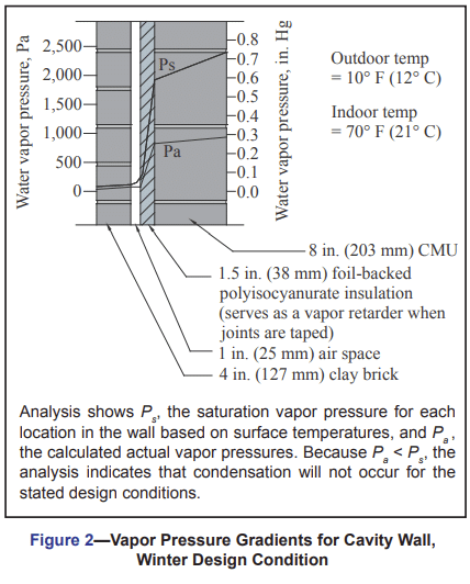
Traditionally, condensation potential has been estimated using steady-state calculations of water vapor pressure and saturation pressures at various points in an assembly. If the calculated vapor pressure exceeds the saturation pressure, condensation is likely to occur if the assumed conditions occur in the field.
This dew point method is a simplified approach which can be used to estimate seasonal mean conditions (rather than daily or even weekly mean conditions) (see Figure 2). However, this method has several disadvantages. For example, wetting and drying cycles cannot be analyzed, since moisture storage within building materials is neglected, as is moisture transfer due to airflow. As a result, the analysis cannot accurately indicate potential damage due to condensation. A complete description of the dew point method is presented in the ASHRAE Handbook, Fundamentals (ref. 6).
Transient computer models which model heat, air and moisture response are an alternative to dew point analyses. They can be used to predict daily or hourly moisture conditions within assemblies. The ASHRAE Handbook, Fundamentals, contains a discussion of input and output parameters, as well as considerations for choosing a program and evaluating the results.
BASEMENTS
Moisture control in basements begins with proper protection from liquid moisture, such as from rain and wet soil. These considerations are addressed in TEK 19-03B, Preventing Water Penetration in Below-Grade Concrete Masonry Walls (ref. 7). If the wall is substantially above grade, condensation control recommendations for the appropriate climate, discussed above, should be followed. If substantially below grade, the basement walls will be dampproofed or waterproofed as required by local code, which essentially acts as an exterior vapor retarder. In this case, an additional interior vapor retarder should be avoided, as this may potentially trap moisture within the wall.
Moisture on the interior of basement walls may be caused by either condensation of interior moisture or leakage of liquid water through the wall. To determine the cause, tape a square of impermeable plastic (such as 6 mil polyethylene) on a portion of the wall experiencing the moisture issues. If there is moisture accumulating under the plastic, an exterior moisture source should be suspected. If moisture forms on top of the plastic, condensation is occurring.
REFERENCES
- Thermal Bridges in Wall Construction, TEK 06-13B, Concrete Masonry & Hardscapes Association, 2010.
- Control of Air Leakage in Concrete Masonry Walls, TEK 06-14A, Concrete Masonry & Hardscapes Association, 2011.
- International Energy Conservation Code. International Code Council, 2009.
- Guide to Determining Climate Regions by County, PNNL17211. Pacific Northwest National Laboratory and Oak Ridge National Laboratory, 2010.
- Building America Best Practices Series: Builders and Buyers Handbook for Improving New Home Efficiency, Comfort, and Durability. U. S. Department of Energy Building Technologies Program. Available at http://www1.eere.energy.gov/buildings/residential/ba_climate_
guidance.html.
5a. Volume 1, Hot and Humid Climates, NREL/TP-550-36960, 2004.
5b. Volume 2, Hot-Dry and Mixed-Dry Climates, NREL/TP550-38360, 2005.
5c. Volume 3, Cold and Very Cold Climates, NREL/TP-550-38309, 2005.
5d. Volume 4, Mixed-Humid Climates, NREL/TP-550-38448, 2005.
5e. Volume 5, Marine Climates, NREL/TP-550-38449, 2006. - ASHRAE Handbook, Fundamentals. American Society of Heating, Refrigerating, and Air-Conditioning Engineers., Inc., 2009.
- Preventing Water Penetration in Below-Grade Concrete Masonry Walls, TEK 19-03B, Concrete Masonry & Hardscapes Association, 2012.
- International Residential Code. International Code Council, 2009.