INTRODUCTION
Radiant heat has long been popular due to its comfort, quiet operation and cleanliness. The radiant element is directly coupled to the adjacent room, with no drafts or convection currents common with forced air systems. Duct noise and dust distribution is also reduced.
Concrete masonry has been successfully used as an integral part of these systems in both residential and commercial applications, as both radiant floors and walls. Hollow concrete masonry cores are aligned and interconnected to form air distribution channels. Heated or cooled air in the channels heats or cools the masonry, which then radiates to the interior space. These systems are generically termed “air core.”
Concrete masonry heats up and cools down slowly, improving comfort by moderating indoor temperature swings and helping shift utility loads to off-peak hours, when utility rates are generally lower. Further economy is provided by using the building’s structure as part of the heating and air-conditioning system. Depending on the application, culls or reclaimed concrete masonry units may be utilized as well.
GENERAL DESIGN GUIDANCE
- To function as designed, the thermal mass of the concrete masonry should be as directly exposed to the interior air as possible. For floors, this means minimizing the use of insulating floor coverings such as carpeting and rugs. Concrete or tile flooring is a better choice in these applications.
- Air core floors or walls can be used with either passive solar heat collection (see ref. 1) or conventional heating and cooling equipment. Air core elements can also be used to destratify, where warm air from the top floor is pulled down to a lower air core floor or wall for cooling.
- It is important that the air core wall or floor be properly installed, and sealed where necessary, to minimize air leakage. When other building materials are integrated into an air core wall or floor, extreme care should be exercised to prevent leakage at joints. Use only high grade sealants and caulks.
- For maximum efficiency, insulate the air core floor or exterior wall from the exterior, or utilize interior walls as air core walls. One possible exception to this rule of thumb is an air core floor on grade in a cooling-dominated climate, where the air core floor is being used as a heat sink.
- Concrete masonry webs are tapered as a result of the manufacturing process. For maximum heat transfer, the concrete masonry units should be placed with the wide end of the taper upstream. This results in a series of small ridges which instills some turbulence to the air flow, increasing the heat transfer to some degree, although also causing a slight pressure drop. These effects should be evaluated for the each project, considering the core area and design air flow rate.
- Where the concrete masonry wall is reinforced, the ungrouted cores can still be used for air flow.
- During humid weather, the masonry also act as a desiccant, absorbing moisture from the air around it. When conditioned air is distributed through the masonry at night or as needed for cooling, it also removes stored moisture from the masonry.
- When outdoor air is used for night cooling, thermal simulation should be performed to determine concrete masonry temperature versus air dew point temperature to prevent situations that could lead to condensation within the walls or floor.
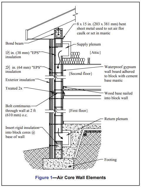
AIR CORE WALLS
Properly insulated exterior walls, such as that shown in Figure 1, may be used for the air core system. Insulating to an R-value of 10 ft2. hr. oF/Btu (1.76 m2.oC/W) greater than that required by local code is recommended. In climates with greater than 6,500 heating degree days (HDD, base 65°F), consider locating the concrete masonry air core walls entirely inside the conditioned space, as interior walls are more thermally efficient in colder climates. The use of solid or solidly grouted concrete masonry exterior walls, insulated on the outside face to provide an R25 (4.4 m2.oC/W) envelope, increases the effectiveness of the mass and reduces the passive solar collection area required for efficient passive solar use.
Sheet metal ducts, where used, should be properly insulated. Some codes may require fuse-link fire dampers as required in active solar air systems. These provide a good safety feature, even if their use is not mandatory. Smoke detectors can also be interfaced with hybrid fans in order to render them inoperable in the event of fire or smoke.
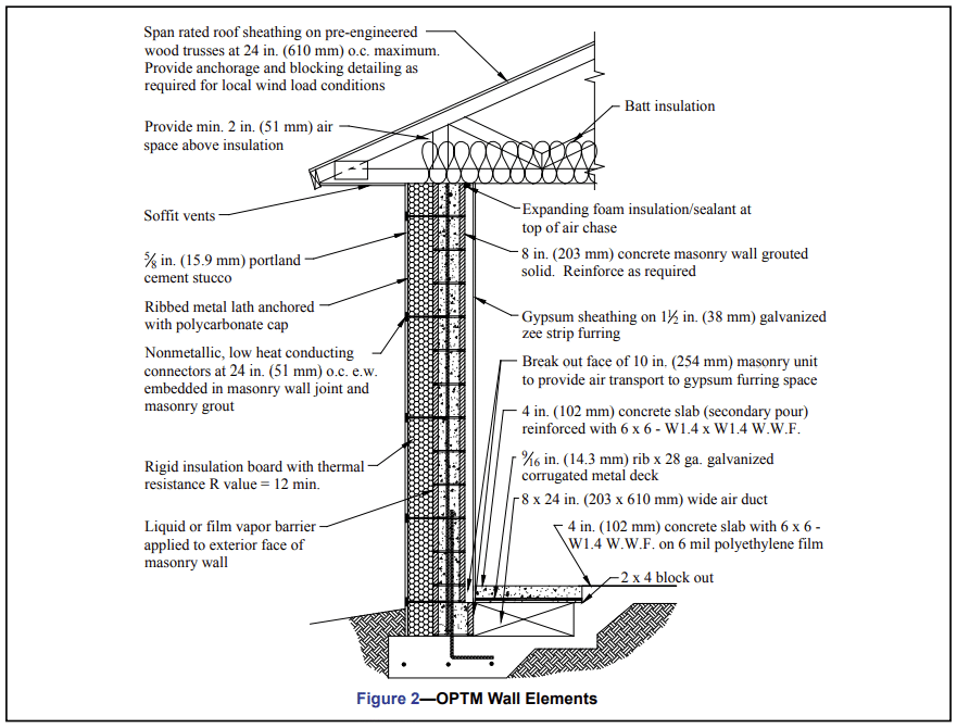
Although air core walls are typically sealed, i.e., air in cores is not distributed within the building interior, some designers have successfully accomplished this by slightly modifying the system. One example is the OPTM (off-peak thermal mass) wall system shown in Figure 2. In this case, a space between the masonry and interior gypsum wallboard is used for conditioned air distribution. This system uses fully grouted concrete masonry with exterior insulation to provide maximum thermal storage capability and isolation from exterior temperatures. To facilitate the flow of conditioned air from the air duct at the base of the wall upward into the space between the gypsum board and the masonry wall, venturis are placed in the air duct at appropriate spacing. (Note that although this system was patented when first developed, the patent has expired.)
AIR CORE FLOORS
Air core floors tend to be less complex than air core walls, so can often be more economical. Air core floors are typically constructed on grade, and finished with a concrete topping. Typical air core floor elements are shown in Figure 3.
Perimeter insulation is a primary factor affecting the performance of air core floors. To prevent excessive heat loss around the perimeter, recommended insulation levels are:
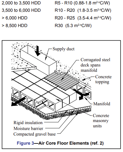
In warmer climates (lower HDD), it may be cost effective to insulate the masonry from high summer soil temperatures, improving its potential for cooling. In colder climates, the high insulation R-value not only improves air core performance, but reduces the overall building heat load.
Below 4,500 HDD, insulation under the floor slab may consist of a simple skirt extending inwards from the foundation approximately 2 to 3 ft (610 to 914 mm).
Continuous under-the-slab insulation is warranted in climates above 4,500 HDD; a minimum of 1 in. (25 mm) of high density extruded board insulation is recommended. The insulation should always be placed on top of a vapor retarder. In climates above 6,000 HDD, 2 to 3 in. (51 to 76 mm) of continuous insulation is recommended; while above 8,000 HDD, it becomes cost effective to use up to 4 in. (102 mm) of insulation to isolate the slab system from the cold soil. Note that these recommendations may not be applicable to floors carrying significant structural loads.
Air leaks should also be minimized by using vapor retarders and thorough caulking and sealing of ducts and plenums.
AIR FLOW
In a single story (8 to 10 ft (2.4- 3.0 m) ceiling height) sunspace or direct gain area serving an air core system, a general rule of thumb for forced air flow is 2 to 5 cfm per square foot (0.61-1.5 m3/min./m2) of collector glazing (glazing area > 7% south glazing/floor area). For taller ceiling heights, the cfm should be increased.
The path length of heat exchanged in the system is used to determine air flow rates. For path lengths of 15 to 20 ft (4.6-6.1 m) through one core of a masonry wall, an air flow of 100 ft/min. (30.5 m/h) for solar heating and 150 ft/min. (45.7 m/h) for mechanically heated air has proven to be satisfactory. Runs in block cores in excess of 20 ft (6.1 m) should be avoided whenever possible. A pressure drop of 0.10 in. (2.5 mm) of water is an indication that the system is performing as desired, while a pressure drop of 0.25 in. (6.4 mm) of water indicates excessive flow restrictions or improper fan size.
In the case of systems expected to store both solar gains and wood burning energy released into room air, two fan speeds should be provided. The faster fan speed should create about 1.5 to 2 times the air flow of the solar fan speed. A proportional fan control based on temperature near the supply inlet could be used, creating a simple variable air volume system.
Flow balancing using small trim tabs at the return plenum side has been used successfully to align core air flow. Large alterations of the air core outlets may result in feedback to change the overall system flow rate, and should be avoided.
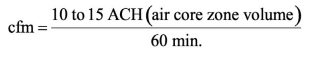
For cooling spaces with ventilation, a general guideline of 10 to 15 air changes per hour (ACH) has been recommended. The air flow generally required for this operation is determined using the relationship:
Cooling a 10 x 14 ft (3.0 x 4.3 m) air core room in this way would require about 200 cfm (5.7 m3/min.). Note that for wholehouse venting, the building air volume can be exchanged by a whole-house fan, while the air core operates in the cooling mode. Different fan speeds may be required for winter and summer operation. Care should be taken to seal all joints, ducts, dampers, housings, fan cages, plenums, slabs, vapor retarders, perimeter insulation and all other fittings.
CONTROLS
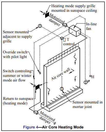
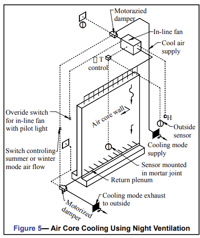
Figures 4 and 5 show fan control methods that have been used with the air core system for heating mode and for cooling using night ventilation, respectively.
Sensors must be placed during construction. It is very difficult to obtain consistent readouts if sensors are installed later by drilling and insertion. Always use a dependable brand of controller similar to those used for active solar systems. Differential controllers for heating should initially be set as follows:
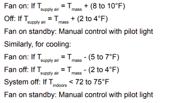
The following temperatures should be continuously monitored for improved system performance: mass, supply air, building air near the thermostat, and outdoor air.
The sensor near the supply grille should be protected from sunlight which can cause faulty readings. A dust filter should be installed if possible; a standard sheet metal box, well insulated and sealed, is satisfactory for enclosing the filter and fan unit. In high solar fraction buildings, an automatic override is recommended. Operation of the solar system should preclude operation of auxiliary equipment, and vice versa.
THERMAL STORAGE CAPACITY
A simple and accurate method for properly sizing distributed thermal mass is diurnal heat capacity (dhc), which is helpful in determining the useful daily energy flux to and from a mass storage system (ref. 3). Using this method, any structure can be properly massed to achieve optimal temperature swings in the 10°F to 12°F (5-6.7 oC) range. Performance is best predicted using computer modelling.
A typical design value of 0.4 Btu/hr. ° F.ft2 (2.27 W/o C.m2) of surface area is used for the heat transfer coefficient of the inside surface areas of the concrete masonry units. Inside the cores, heat transfer is convectively dominated during charging, with some radiative coupling from shell to shell during discharge. The proper sizing and distribution of thermal mass in passive solar applications is discussed in reference 1.
REFERENCES
- Passive Solar Design Strategies, TEK 06-05A, Concrete Masonry & Hardscapes Association, 2006.
- Howard, B. D. The Air-Core System for Thermal Storage. Passive Solar Journal. Marcel Dekker and ASES, Vol. 3 No. 3, 1986.
- Balcomb, J.D., 1982, ‘ Heat Storage Effectiveness of Concrete Masonry Units.’’