INTRODUCTION
Single wythe concrete masonry walls are often constructed of hollow units with cores filled with insulation and/or grout. This construction method allows insulation and reinforcement to be used to increase thermal and structural performance, respectively, without increasing the wall thickness.
U-factors and R-values are used to estimate heat flow under steady state conditions (neglecting the effects of thermal mass). These steady-state values can be used in conjunction with factors such as thermal mass, climate, and building orientation to estimate a building envelope’s thermal performance, typically using software.
This TEK lists thermal resistance (R) and thermal transmittance (U) values of single wythe walls. Cavity wall R-values are listed in TEK 06-01C, R-Values of Multi-Wythe Concrete Masonry Walls (ref. 1).
The R-values/U-factors listed in this TEK were determined by calculation using the code-recognized series-parallel (also called isothermal planes) calculation method (refs. 2, 3, 4). The method accounts for the thermal bridging (energy loss) that occurs through the webs of concrete masonry units. The method is fully described in TEK 06-01C. Alternate code approved means of determining R values of concrete masonry walls include two-dimensional calculations and testing (ref. 2).
CONCRETE MASONRY ENERGY PERFORMANCE
Although this TEK presents a compendium of concrete masonry assembly R-values and U-factors, it is important to note that R values/U-factors alone do not fully describe the thermal performance of a concrete masonry assembly.
Concrete masonry’s thermal performance depends on both its steady state thermal characteristics (described by R-value or U-factor) as well as its thermal mass (heat capacity) characteristics. The steady state and mass performance are influenced by the size, type, and configuration of masonry unit, type and location of insulation, finish materials, density of masonry, climate, and building orientation and exposure conditions.
Thermal mass describes the ability of materials to store energy. Because of its comparatively high density and specific heat, masonry provides very effective thermal storage. Masonry walls retain their temperature long after the heat or air-conditioning has shut off. This, in turn, effectively reduces heating and cooling loads, moderates indoor temperature swings, and shifts heating and cooling loads to off-peak hours.
Due to the significant benefits of concrete masonry’s inherent thermal mass, concrete masonry buildings can provide similar energy performance to more heavily insulated light frame buildings.
These thermal mass effects have been incorporated into energy code requirements as well as sophisticated computer models. Due to the thermal mass, energy codes and standards such as the International Energy Conservation Code (IECC) (ref. 5) and Energy Efficient Standard for Buildings Except Low-Rise Residential Buildings, ASHRAE Standard 90.1 (ref. 2), require less insulation in concrete masonry assemblies than equivalent light-frame systems. Although applicable to all climates, the greater benefits of thermal mass tend to be found in warmer climates (lower-numbered Climate Zones).
Although the thermal mass and inherent R-value/U-factor of concrete masonry may be enough to meet energy code requirements (particularly in warmer climates), concrete masonry assemblies may require additional insulation, particularly when designed under more contemporary building code requirements or to achieve above-code thermal performance. For such conditions, there are many options available for insulating concrete masonry construction.
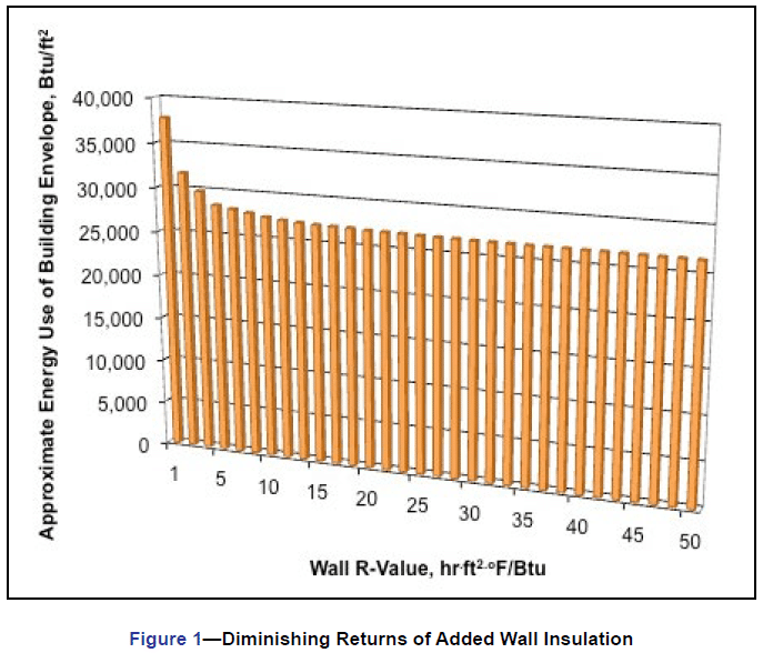
Although in general higher R-values reduce energy flow through a building element, R-values have a diminishing impact on the overall building envelope energy use. In other words, it’s important not to automatically equate higher R-value with improved energy efficiency. As an example, consider a two story elementary school in Bowling Green, Kentucky. If this school is built using single wythe concrete masonry walls with cell insulation only and a resulting wall R-value of 7 hr.ft2.oF/Btu (1.23 m2.K/W), an estimate of the building envelope energy use for this structure is approximately 27,800 Btu/ft2 (87.7 kW.h/m2), as shown in Figure 1. If we increase the R-value of the wall to R14 by adding additional insulation while holding the other envelope variables constant, the building envelope energy use drops by only 2.5%, which is not in proportion to doubling the wall R-value. Figure 1 illustrates this trend: as wall R-value increases, it has less and less impact on the building envelope thermal performance.
In this example, a wall R-value larger than about R12 no longer has a significant impact on the envelope energy use. At this point, it makes more sense to invest in energy efficiency measures other than wall insulation.
When required, concrete masonry can provide assemblies with R values that exceed code minimums. For overall project economy, however, the industry recommends balancing needs and performance expectations with reasonable insulation levels.
ENERGY CODE COMPLIANCE
Compliance with prescriptive energy code requirements can be demonstrated by:
- the concrete masonry wall by itself or the concrete masonry wall plus a prescribed R-value of added insulation, or
- the overall U-factor of the wall.
The IECC prescriptive R-value table calls for “continuous insulation” on concrete masonry and other mass walls. This refers to insulation uninterrupted by furring or by the webs of concrete masonry units. Examples of continuous insulation include rigid insulation adhered to the interior of the wall with furring and drywall applied over the insulation, continuous insulation in the cavity of a masonry cavity wall, and exterior insulation and finish systems. These and other insulation options for concrete masonry assemblies are discussed in TEK 06 11A, Insulating Concrete Masonry Walls (ref. 6).
If the concrete masonry assembly will not include continuous insulation, there are several other options to comply with the IECC requirements—concrete masonry assemblies are not required to have continuous insulation in order to meet the IECC, regardless of climate zone.
Other compliance methods include: prescriptive U-factor tables, and computer programs which may require U-factors and heat capacity (a property used to indicate the amount of thermal mass) to be input for concrete masonry walls. See TEK 06-04B, Energy Code Compliance Using COMcheck, (ref. 7) for more detailed information. Another compliance method, the energy cost budget method, incorporates sophisticated modeling to estimate a building’s annual energy cost.
A more complete discussion of concrete masonry IECC compliance can be found in TEK 06-12E (for the 2012 IECC) (ref. 8).
CONCRETE MASONRY UNIT CONFIGURATIONS
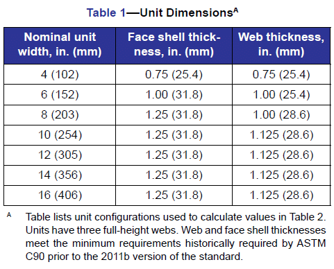
Revisions in 2011 to ASTM C90¸ Standard Specification for Loadbearing Concrete Masonry Units (ref. 9) have significantly reduced the minimum amount of web material required for CMU. Values in this TEK are based on concrete masonry units with three webs, with each web being the full height of the unit, and having a minimum thickness as provided in historical versions of ASTM C90 (see Table 1).
The changes in C90, however, allow a much wider range of web configurations, with corresponding changes in R-values and U-factors (because the webs of a CMU act as thermal bridges, reducing the CMU web area increases the R-value of the corresponding concrete masonry assembly). More discussion on the impact of web configuration and thermal performance can be found in CMU-TEC 001-23, Concrete Masonry Unit Shapes, Sizes, Properties, and Specifications (ref. 10).
The Thermal Catalog of Concrete Masonry Assemblies (ref.11) lists R-values and U-factors of traditional units, as included here, as well as wall assemblies with smaller web areas, as now allowed by ASTM C90. The additional wall assemblies are based on:
- CMU having two full-height 3/4 in. (19 mm) thick webs, and
- a ‘hybrid’ system of CMU, intended to maximize thermal efficiency. The hybrid system uses the two-web units described above for areas requiring a grouted cell, and a one-web unit where grout confinement is not required.
Although the R-values/U-factors in Table 2 are based on typical 8-in. (203-mm) high concrete masonry units, 4-in. (102 mm) high units (commonly called “half-high” units) are also widely available, and other heights may be available in some markets. Because the wall R values vary so little with different unit heights, the values in Table 2 can be applied to units with heights other than 8 in. (203 mm).
U-FACTOR AND R-VALUE TABLES – TRADITIONAL THREE-WEB UNITS
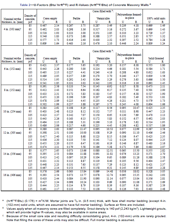
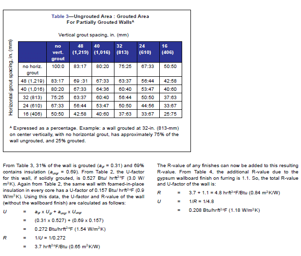
Table 2 lists calculated U-factors and R-values of various thicknesses of concrete masonry walls, for concrete densities of 85 to 135 lb/ft3 (1,362 to 2,163 kg/m3), with various core fills. Table 3 shows the approximate percentage of grouted and ungrouted wall area for different vertical and horizontal grout spacings, which can be used to determine R-values of partially grouted walls (see following section).
In addition to the core insulations listed across the top of Table 2, polystyrene inserts are available which fit in the cores of concrete masonry units. Inserts are available in many shapes and sizes to provide a range of insulating values and accommodate various construction conditions. Specially designed concrete masonry units may incorporate reduced height webs to accommodate inserts. Such webs also reduce thermal bridging through masonry, since the reduced web area provides a smaller cross-sectional area for energy flow. To further reduce thermal bridging, some manufacturers have developed units with two webs rather than three. In addition, some inserts have building code approval to be left in the grouted cores, thus improving the thermal performance of fully or partially grouted masonry walls.
The values for insulated and grouted cores in Table 2 are based on the assumption that all masonry cores are insulated or grouted, respectively. In other words, for ungrouted walls and fully grouted, the values in Table 2 can be used directly. For partially grouted walls, refer to the following section.
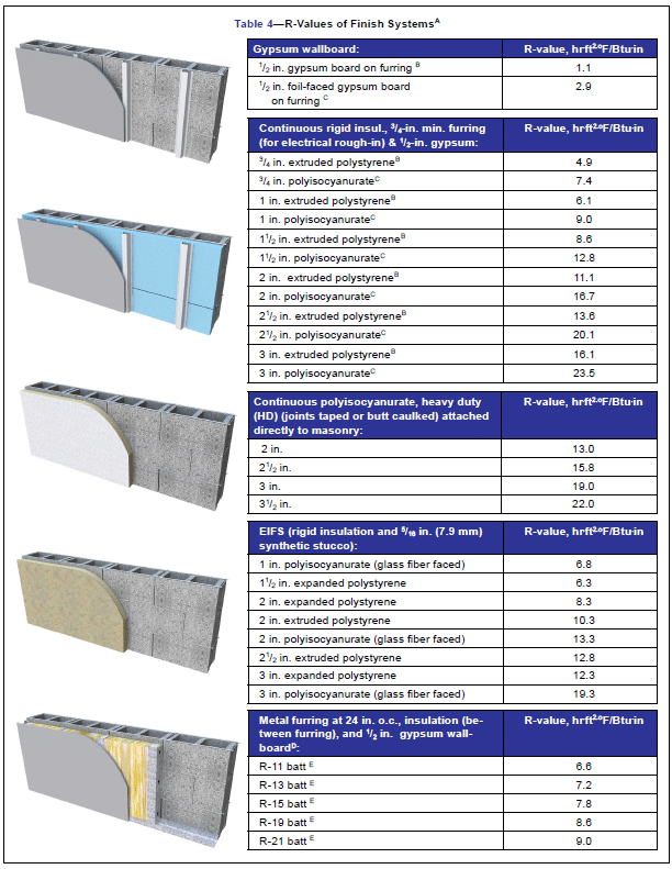
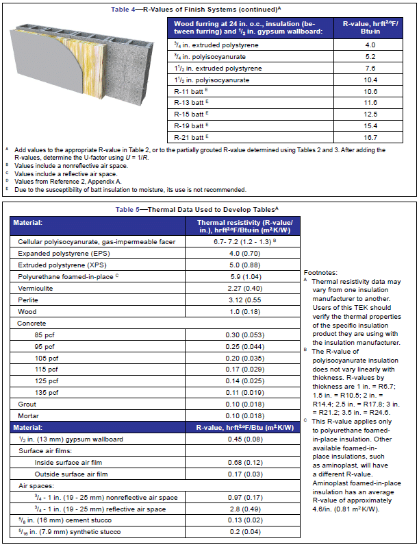
R-values of various interior and exterior insulation and finish systems are listed in Table 4. (Note that the use of batt insulation is not recommended, due to its susceptibility moisture.) These R-values can be added to the wall R-values in Table 2. After adding the R-values, the wall U-factor can be found by inverting the total R-value (i.e., U = 1 /R) (see also the following example). Note that tables of precalculated R-values and U-factors, including the various insulation and finish systems, are available in Thermal Catalog of Concrete Masonry Assemblies.
Thermal properties used to compile the tables are listed in Table 5.
R-VALUES AND U-FACTORS OF PARTIALLY GROUTED CONCRETE MASONRY
For partially grouted walls, the values in Table 2 must be modified to account for the grouted cores, using an area weighted average approach. The first step is to determine how much of the wall area is grouted (see Table 3). The U-factor of the wall is calculated from the area-weighted average of the U-factors of the grouted area and ungrouted areas as follows:
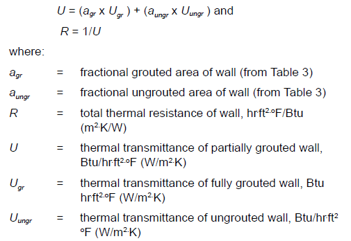
For example, consider an 8 in. (203 mm) wall composed of hollow 105 lb/ft3 (1682 kg/m3) concrete masonry, and grouted at 48 in. (1,219 mm) o.c. both vertically and horizontally. The ungrouted cores contain polyurethane foamed-in-place insulation, and the wall is finished on the interior with gypsum wallboard.
REFERENCES
- R-Values of Multi-Wythe Concrete Masonry Walls, TEK 06-01C, Concrete Masonry & Hardscapes Association, 2013.
- Energy Standard for Buildings Except Low-Rise Residential
Buildings, ANSI/ASHRAE/IESNA 90.1-2010. American Society of Heating, Refrigerating and Air-Conditioning Engineers, Inc., 2010. - ASHRAE Handbook, Fundamentals. American Society of Heating, Refrigerating and Air-Conditioning Engineers, Inc., 2009.
- Guide to Thermal Properties of Concrete and Masonry Systems. ACI 122R-02. American Concrete Institute, 2002.
- International Energy Conservation Code. International Code Council, 2006, 2009, 2012.
- Insulating Concrete Masonry Walls, TEK 06-11A, Concrete
Masonry & Hardscapes Association, 2010. - Energy Code Compliance Using COMcheck, TEK 06-04B, Concrete Masonry & Hardscapes Association, 2012.
- Concrete Masonry in the 2012 Edition of the IECC, TEK 06-12E, Concrete Masonry & Hardscapes Association, 2012.
- Standard Specification for Loadbearing Concrete Masonry Units, ASTM C90-11. ASTM International, 2011.
- Concrete Masonry Unit Shapes, Sizes, Properties, and Specifications, CMU-TEC-001-23, Concrete Masonry & Hardscapes Association, 2023.
- Thermal Catalog of Concrete Masonry Assemblies, Second Edition, CMU-MAN-004-12, Concrete Masonry & Hardscapes Association, 2012.