INTRODUCTION
Although concrete masonry structures can be constructed using virtually any layout dimension, for maximum construction efficiency and economy, concrete masonry elements should be designed and constructed with modular coordination in mind. Modular coordination is the practice of laying out and dimensioning structures and elements to standard lengths and heights to accommodate modular-sized building materials. When modular coordination is not considered during the design phase, jobsite decisions must be made—often in haste and at a cost. This TEK provides recommendations for planning masonry construction to minimize cutting of masonry units or using nonstandard unit sizes.
When a project does require non-modular layout, further design and construction issues need to be addressed, including:
Placement of vertical reinforcement—In construction containing vertical reinforcing steel, the laying of units in other than running (half) bond or stack bond interrupts the vertical alignment of unit cells. As a result, reinforcement placement and adequate consolidation of grout becomes difficult, and partial grouting of walls is virtually impossible.
Interruption of bond pattern—In addition to the aesthetic impact a change in bond pattern can create, building codes often contain different design assumptions for masonry constructed in running bond versus other bond patterns. Walls incorporating more than a single bond pattern may present a unique design situation.
Locating control joints—In running bond, control joint construction can be accomplished using only full and half-size units. Similarly, stack bond construction only requires full-size units when control joints are properly spaced and detailed. However, with other bond patterns units may need to be cut if specially dimensioned units are not used or are not available.
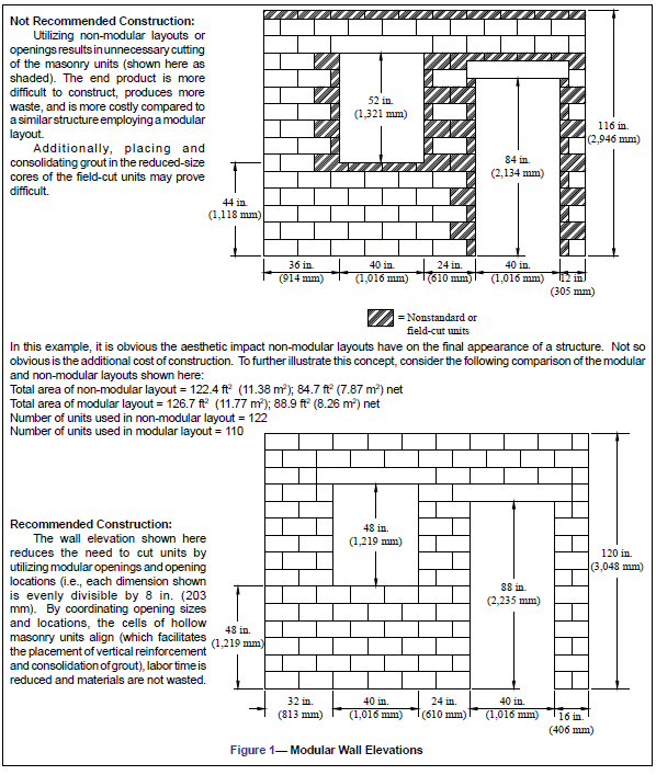
MODULAR WALL ELEVATIONS
Standard concrete masonry modules are typically 8 in. (203 mm) vertically and horizontally, but may also include 4-in. (102 mm) modules for some applications. These modules provide overall design flexibility and coordination with other building products such as windows, doors, and other similar elements as shown in Figures 1 and 2.
MODULAR WALL OPENINGS
The rough opening dimensions illustrated in Figure 1 apply to the layout and construction of the masonry. To allow for fastening windows and doors to the masonry, however, the nominal heights and widths of these elements are slightly less.
For conventional construction methods, the widths of masonry openings for doors and windows should generally be 4 in. (102 mm) larger than the door or window width. This allows for 2 in. (51 mm) on each side of the opening for framing. The heights of masonry openings to accommodate windows are typically 8 in. (203 mm) greater than the window height. This opening size allows for 2 in. (51 mm) above and below for framing and 4 in. (102 mm) for installation of a sill at the bottom of the window. Masonry openings for doors are commonly either 2 or 4 in. (51 or 102 mm) greater than the door height, allowing for the door framing as well as the use of a standard sized door.
Thus, door and window widths of 28, 36, 44, and 52 in. (711, 914, 1,118 and 1,321 mm) (and so on in 8 in. (203 mm) increments) do not require the masonry to be cut. Modular window heights are any multiple of 8 in. (203 mm), with a masonry window opening 8 in. (203 mm) greater than the height of the window if a 4-in. (102 mm) sill will be used. Similarly, door heights 2 in. (51 mm) less than any even multiple of eight can be installed without the need for cutting the masonry. For the commonly available 84-in. (2,134 mm) high door, a 4-in. (102 mm) door buck can be placed at the top of the opening. In addition, precast lintels are available in some areas containing a 2 in. (51 mm) notch to accommodate 80-in. (2,032 mm) doors.
Hollow metal frames for doors should be ordered and delivered
for the masonry before the other door frames in the project are scheduled for delivery. For economy, the frames should be set before the walls are built. If the walls are built before the frame are set, additional costs are incurred to set special knock down door frames and attachments.
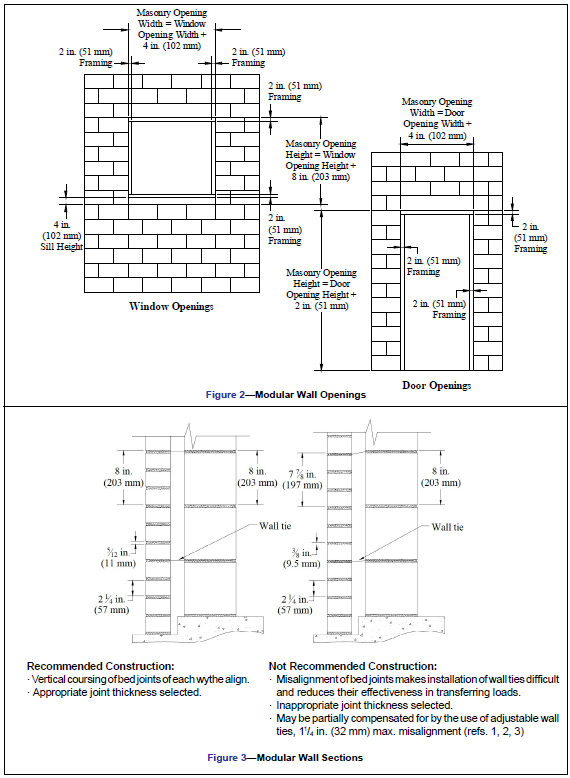
MODULAR WALL SECTIONS
For door and window openings, the module size for bond patterns and layout are nominal dimensions. Actual dimensions of concrete masonry units are typically 3/8 in. (9.5 mm) less than nominal dimensions, so that the 4 or 8-in. (102 or 203 mm) module is maintained with 3/8 in. (9.5 mm) mortar joints. Where mortar joint thicknesses differ from 3/8 in. (9.5 mm) (as may be specified for aesthetic purposes or with brick construction), special consideration is required to maintain modular design. Figure 3 illustrates this concept.
Typically, concrete masonry units have nominal face dimensions of (height by length) 8 by 16 in. (203 by 406 mm), and are available in nominal widths ranging from 4 in. to 16 in. (102 to 406 mm) in 2-in. (51 mm) increments. In addition to these standard sizes, other unit widths, heights and lengths may be available from concrete masonry producers. The designer should always check local availability of specialty units prior to design.
Incorporating brick into a project, either as a structural component or as a veneer, can present unique modular coordination considerations in addition to those present with single wythe construction. Brick most commonly have a nominal width of 4 in. (102 mm), length varying from 8 to 16 in. (203 to 406 mm) and height from 2 1/2 to 6 in. (64 to 152 mm). The specified dimensions of modular concrete and clay brick are typically 3 5/8 by 2 1/4 by 7 5/8 in. (92 by 57 by 194 mm), but may be available in a wide range of dimensions.
Because of their unique dimensions, concrete and clay brick are usually laid with bed joints that are slightly larger (or sometimes smaller depending upon the actual size of the brick) than the standard 3/8 in. (9.5 mm) mortar joint thickness. For example, common modular brick are laid with a 5/12 in. (11 mm) thick bed joint, thereby providing a constructed height of 2 2/3 in. (68 mm) for one brick and one mortar joint. (Note that a 5/12 in. (11 mm) thick bed joint is within allowable mortar joint tolerances (refs. 1, 2).) The result is that three courses of brick (including the mortar joints) equals one 8-in. (203 mm) high module, thereby maintaining modular coordination (see Figure 3).
MODULAR BUILDING LAYOUTS AND HORIZONTAL COURSING
In addition to wall elevations, sections and openings, the overall plan dimensions of a structure also need to be considered, especially when using units having nominal widths other than 8 in. (203 mm).
Ideally, the nominal plan dimensions of masonry structures should be evenly divisible by 8 in. (203 mm). This allows constructing each course of a wall using only full-length or half length units, which in turn reduces labor and material costs. In addition, maintaining an 8-in. (203 mm) module over the length of a wall facilitates the turning of corners, whereby half of the units from one wall interlock with half of the units from the intersecting wall. As an alternative to cutting units or changing building dimensions, corner block can be used if available. These units are specifically manufactured to turn corners without interrupting bond patterns. Concrete Masonry Corner Details,TEK 05-09A (ref. 4) contains a variety of alternatives for efficiently constructing corners.
METRIC COORDINATION
One additional consideration for some projects is the use of standard sized (inch-pound) masonry units in a metric project. Similar to inch pound units, masonry units produced to metric dimensions are 10 mm (13/32 in.) less than the nominal dimensions to provide for the mortar joints. Thus, the nominal metric equivalent of an 8 by 8 by 16 in. unit is 200 by 200 by 400 mm (190 by 190 by 390 mm net unit dimensions). Since inch-pound dimensioned concrete masonry units are approximately 2% larger than hard metric units, complications can arise if they are incorporated into a structure designed on a 100 mm (3.9 in.) metric module, or vice versa.
REFERENCES
- International Building Code. International Code Council,
2003 and 2006. - Specification for Masonry Structures, ACI 530.1-05/ASCE
6-05/TMS 602-05. Reported by the Masonry Standards
Joint Committee, 2005. - Building Code Requirements for Masonry Structures, ACI
530-05/ASCE 5-05/TMS 402-05. Reported by the Masonry
Standards Joint Committee, 2005. - Concrete Masonry Corner Details, TEK 05-09A, Concrete
Masonry & Hardscapes Association, 2004.