
INTRODUCTION
High winds subject buildings to large horizontal forces as well as to significant uplift. Reinforced concrete masonry is well suited to resist the large uplift and overturning forces due to its relatively large mass.
High wind provisions generally apply to areas where the design wind speed is over 100 mph (161 km/hr) and over three second gust as defined by ASCE 7 (ref. 10). The enclosed details represent prescriptive minimum requirements for concrete masonry buildings, based on Standard for Hurricane Resistant Residential Construction (ref. 3).
CONTINUOUS LOAD PATH
Connections between individual building elements—roof, walls, floors and foundation—are critical to maintaining structural continuity during a high wind event. The critical damage to buildings in such events typically occurs due to uplift on the roof, resulting in the loss of crucial diaphragm support at the top of the wall. A primary goal for buildings subjected to high winds is to maintain a continuous load path from the roof to the foundation. This allows wind uplift forces on the roof to be safely distributed through the walls to the foundation. If one part of the load path fails or is discontinuous, building failure may occur.
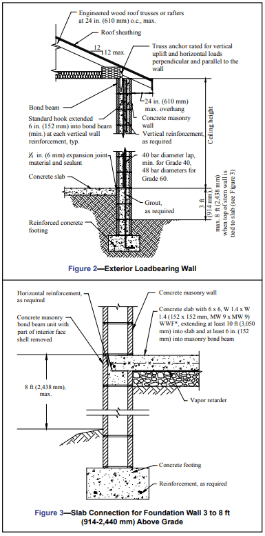
Proper detailing and installation of mechanical connectors is necessary for maintaining continuous load paths. Note that in order for connectors to provide their rated load capacity, they must be installed according to the manufacturer’s or building code specifications. In coastal areas, corrosion protection is especially important due to the corrosive environment. Note that water penetration details are not specifically highlighted in the following details. The reader is referred to references 7 through 9 for more information on preventing water penetration in concrete masonry walls. In addition to a continuously reinforced bond beam at the top of the wall around the entire perimeter of the building, vertical reinforcement must be placed throughout a wall to resist the high uplift loads and provide continuity, including: at corners and wall intersections; on each side of openings wider than 6 ft (1,829 mm); at the ends of shear segments; and where girders or girder trusses bear on the concrete masonry wall (refs. 3, 4). Each of the exterior walls on all four sides of the building and all interior walls designed as shear walls must have at least one 2 ft (610 mm) minimum section of wall identified as a shear segment to resist the high lateral loads. Longer shear segments are more effective and are recommended where possible or required by design. See Figure 1 for a summary of reinforcement requirements (ref. 3).
Reinforcement must be properly spliced to provide load path continuity. Using allowable stress design, a splice length of 40 bar diameters is required by Building Code Requirements for Masonry Structures (ref. 1) for Grade 40 reinforcement and 48 bar diameters for Grade 60 reinforcement. If the wall was designed assuming Grade 40 and Grade 60 was used for construction, however, the 40 bar diameter lap splice may still be used. See Steel Reinforcement for Concrete Masonry, TEK 12-04D (ref. 5) for standard hook requirements.

DETAILS
Exterior Loadbearing Wall
Figure 2 shows a typical loadbearing wall with a floating floor slab. Vertical reinforcement should be placed in the center of the concrete masonry cores to adequately resist both positive and negative wind pressures. Bond beam depth and minimum horizontal reinforcement varies with design wind velocity, ceiling height, roof truss span and spacing of vertical wall reinforcement. Since wind suction forces on the leeward side of a building can be essentially as high as the pressure forces on the windward side, limitations are placed on the height above grade. However, if the slab is laterally supported and tied to the concrete masonry foundation wall as shown in Figure 3, the foundation wall may be extended to 8 ft (2,440 mm) above grade (ref. 3).
Roof Truss Anchor
Figure 4 shows a typical roof truss anchor cast into the bond beam of a concrete masonry bearing wall. The required anchor load capacity depends on the design wind speed as well as the roof truss span. In addition to being rated for uplift, the anchor must be rated for horizontal forces parallel to the wall (in-plane) and perpendicular to the wall (out-of-plane).
Often, the direct embedded roof truss anchor method of connecting the roof to walls is preferred over the bolted top plate and hurricane clip method, as it generally has greater capacity and fewer connections. Additionally, the nail area available for the hurricane clip is limited by the thickness of the top plate.
Bolted Top Plate
As an alternate to the roof truss anchor, a bolted top plate may be used for the roof to wall connection (see Figure 5); however, anchor bolt spacing must be reduced (24 in. (610 mm) maximum) because the top plate is loaded in its weak direction. The detail illustrates several different connector types that are commonly used to connect the truss to the top plate.
Gable End Walls
Because of their exposure, gable end walls are more prone to damage than are hipped roofs unless the joint at the top of the end wall and the bottom of the gable (see Figure 6b) is laterally supported for both inward and outward forces. Figure 6a shows a continuous masonry gable end wall using either a raked concrete bond beam or a cut masonry bond beam along the top of full height reinforced concrete masonry gable end walls.
As an alternative, a braced gable end wall can be constructed as shown in Figure 6b by stopping the masonry of the gable end at the eave height and then using conventional wood framing to the roof diaphragm. However, unless the end wall is properly braced to provide the necessary lateral support as shown in Figure 6b, this results in a weak point at the juncture of the two materials with little capacity to resist the high lateral loads produced by high winds. The number and spacing of braces depends on design wind speed, roof slope and roof span (ref. 2, 3, 6).
Gable End Wall Overhangs
Figure 7a shows a continuously reinforced castin-place concrete rake beam along the top of the gable end wall. The beam is formed over uncut block in courses successively shortened to match the slope of the roof. A minimum of 4 in. (102 mm) is needed from the highest projected corner of block to the top of the beam. Reinforcement that is continuous with the bond beam reinforcement in the side walls is placed in the top of the beam. In this detail, an outlooker type overhang is shown where the rake beam is constructed 3½ in. (89 mm) lower than the trusses so that a pressure treated 2 x 4 (38 x 89 mm) can pass over it. A ladder type overhang detail also can be used with the concrete rake beam where the beam is constructed to the same height as the trusses similar to that shown for the cut masonry rake beam in Figure 7b.
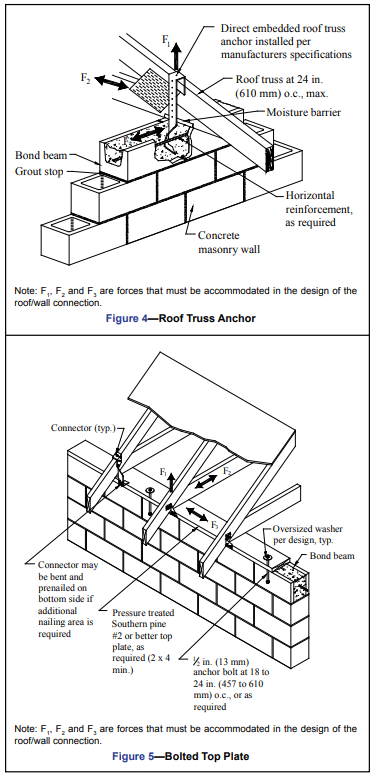
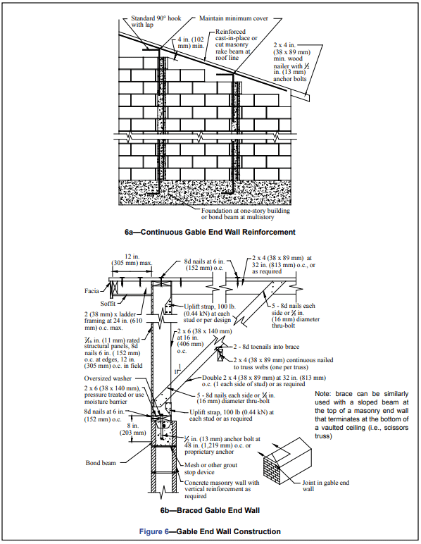
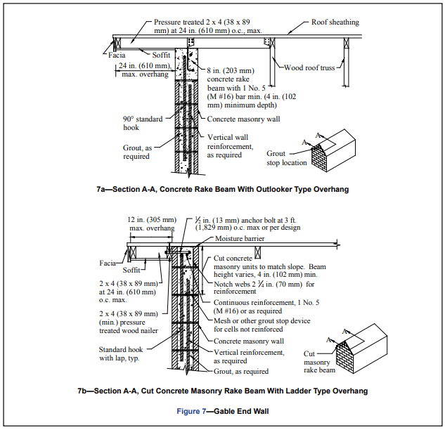
Figure 7b shows a continuously reinforced cut masonry rake beam along the top of the gable end wall. Masonry units are cut to conform to the roof slope at the same height as the roof trusses. A 2 ¾ in. (70 mm) deep notch is cut into the tops of the concrete masonry webs to allow placement of reinforcement that is continuous with the bond beam reinforcement in the side walls. A minimum of height of 4 in. (102 mm) is needed for the cut masonry bond beam. In this figure, a ladder type overhang is shown. However, an outlooker type overhang detail can be used similar to that shown for the cast-in-place concrete rake beam in Figure 7a.
REFERENCES
- Building Code Requirements for Masonry Structures, ACI
530-02/ASCE 5-02/TMS 402-02. Reported by the Masonry
Standards Joint Committee, 2002. - The Guide to Concrete Masonry Residential Construction
in High Wind Areas. Florida Concrete & Products
Association, Inc., 1997. - Standard for Hurricane Resistant Residential Construction,
SSTD 10-99. Southern Building Code Congress
International, Inc., 1999. - 2000 International Building Code. International Code
Council, 2000. - Steel Reinforcement for Concrete Masonry, TEK 12-04D.
Concrete Masonry & Hardscapes Association, 2002. - Annotated Design and Construction Details for Concrete
Masonry, CMU-MAN-001-23. Concrete Masonry &
Hardscapes Association, 2003. - Design for Dry Single-Wythe Concrete Masonry
Walls, TEK 19-02B. Concrete Masonry & Hardscapes
Association, 2012. - Flashing Strategies for Concrete Masonry Walls, TEK 19-
04A. Concrete Masonry & Hardscapes Association, 2003. - Flashing Details for Concrete Masonry Walls, TEK 19-05A.
Concrete Masonry & Hardscapes Association, 2008. - Minimum Design Loads for Buildings and Other
Structures, ASCE 7-02. American Society of Civil
Engineers, 2002.