INTRODUCTION
Concrete masonry units are uniquely suited to distinctive aesthetically-pleasing architectural features. The almost limitless variety of sizes, shapes, textures, colors and surface treatments has made concrete masonry one of the most versatile and sought after building materials today. In addition, the relatively small unit size lends itself to unique applications, such as radial walls.
The use of concrete masonry in the design and construction of radial walls presents a unique challenge to the design professional. Where curved walls once were formed from handhewn stone carved to fit a predetermined radius, radial walls of concrete masonry are usually formed from rectangular units of fixed shape and dimension. The end result is a series of short chords rather than a smooth arc. The greater the radius, the more closely the surface formed by the chords approaches that of a true arc.
The curvature of these walls depends on variables such as the length and thickness of the concrete masonry unit, the width of the vertical head joints at the interior and exterior wall faces and whether the units will be used as is, beveled at the ends, or cut to conform to the desired radius.
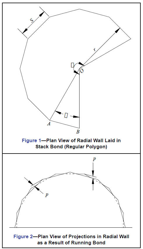
The bond pattern also impacts the overall appearance of a curved wall section. Curved walls laid up in stack bond (i.e., with vertical head joints aligned) possess the geometric properties of a regular polygon (Figure 1). Walls laid up in running bond (with offset head joints), on the other hand, exhibit a similar geometric configuration at the individual courses with the exception that the ends of units in alternating courses project out beyond the faces of the units immediately above and below (Figure 2). These projections create a basketweave effect which may or may not contribute to the aesthetic value of the wall.
This TEK contains information to help the designer determine the best way to construct a curved concrete masonry wall, based on factors such as: desired radius, unit size, mortar joint size, projection size for running bond and the effect of cutting the units. Note that these recommendations apply to the physical limitations and geometry of constructing radial walls.
The designer must ensure any radial wall design complies with all applicable building code requirements.
Although this TEK focuses on the construction of radial walls using conventional concrete masonry units, note that beveled units or other special shapes may be available to facilitate masonry radial wall construction as well.
MINIMUM WALL RADIUS
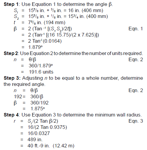
The minimum radii for curved or circular walls constructed of concrete masonry units is determined through iterations of the plane rectilinear geometric formulae for regular polygons. These equations are:
β = 2 (Tan -1 [(S1 S2)/2t]) Eqn. 1
n = θ/β Eqn. 2
r = Sl /(2 Tan β/2) Eqn. 3
Example
Nominal 8 x 8 x 16-in. (203 x 203 x 406-mm) concrete masonry units are being considered for use in a circular wall. Actual unit dimensions are 155/8 in. (397 mm) length and 75/8 in. (194 mm) width, and the exterior mortar joint is to be 3/8 in. (9.5 mm). The width of the interior mortar joint is to be 1/8 in. (3.2 mm). What is the smallest radius the circular wall can be constructed to without cutting the units?
Although the equations remain the same, there are several practical methods to vary the minimum radii of curved or circular concrete masonry walls:
- Reduce the length of the units. Changing from a 16-in. (406-mm) long unit to an 8-in. (203-mm) long unit will reduce the minimum radius by half.
- Vary the mortar joint width. An increase in the mortar joint width at the exterior wall face, with or without a decrease in mortar joint width at the interior wall face, reduces the radius as well as the number of units required. Although it is generally recommended that the width of the mortar joint at the interior face not be less than 1/8 in. (3.2 mm), this may be acceptable under certain circumstances.
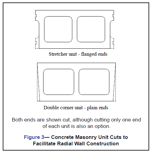
- Shorten the length of the units at the interior face. Cutting the units is practical if stretcher units with flanged ends are used. Cutting is less practical for double corner units with plain ends (see Figure 3).
Projections
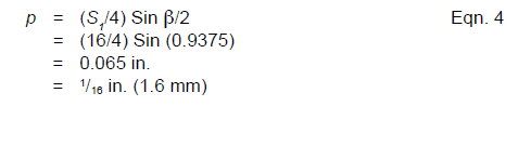
For a curved masonry wall laid in running bond, it may be desirable to limit the projections of the unit corners beyond the unit faces in the courses above and below for reasons of aesthetics. Generally, projections of approximately 1/8 in. (3.2 mm) for nominal 8 in. (203 mm) long units and 1/4 in. (6.4 mm) for nominal 16 in. (406 mm) long units are considered acceptable. If the wall surface is to be stuccoed or otherwise covered, projections of 1/2 in. to 3/4 in. (13 to 19 mm) may be acceptable. Minimizing projections to less than 1/8 in. (3.2 mm) is usually not practical because of construction tolerances.
The projection of the unit corners for the previous example is found by using Equation 4.
DESIGN TABLES
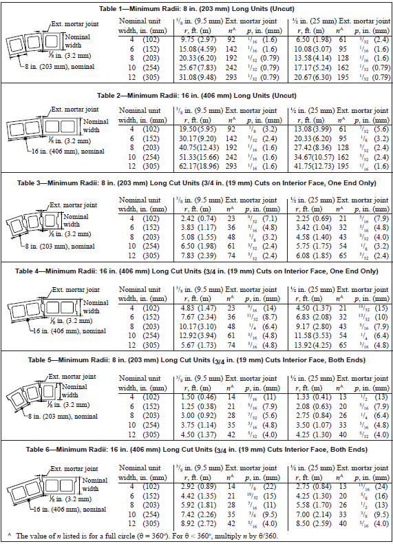
Tables 1 through 6 list the minimum radii, number of units and length of projection for circular concrete masonry walls, based on using either a 3/8 in. (9.5 mm) or 1/2 in. (13 mm) wide exterior head joint. Using the larger exterior head joint width allows for smaller radii. All tables assume that the interior head joint width is 1/8 in. (3.2 mm). Tables 1 and 2 present this data for 8 in. (203 mm) and 16 in. (406 mm) long units which have not been cut (as shown in Figure 3), respectively.
Similar data for units cut as shown in Figure 3 are listed in Tables 3 through 6.
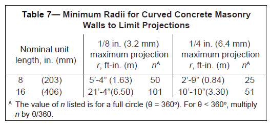
Table 7 should be consulted when the size of the projection is a prime consideration. These tables list the minimum radii and number of units required to limit projections to 1/8 in. (3.2 mm) and 1/4 in. (6.4 mm) for nominal 8-in. (203 mm) and 16 in. (406 mm) long units.
Construction and unit manufacturing tolerances are such that the radii provided in the Tables may vary by + 1 in. (25 mm).
NOTATIONS
n = Number of concrete masonry units to complete the arc for the central angle θ. The number of units for the arc should be a whole number.
p = for masonry laid in running bond, projection of masonry unit corners beyond the faces of the units in the courses above and below (see also Figure 2), in. (mm)
r = radius to the exterior face of the wall, measured to the midpoint of a unit, in. (mm)
S1 = length of each side of the polygon forming the exterior face of the wall (length of the unit plus the width of one exterior mortar joint), in. (mm)
S2 = length of each side of the polygon forming the interior face of the wall (length of the unit plus the width of one interior mortar joint), in. (mm)
t = actual unit thickness, in. (mm)
β = the angle subtended by one side of a polygon (length of one concrete masonry unit), see AOB in Figure 1, degrees
θ = central angle subtended for the complete arc of the curved wall (equals 360o for a complete circle), degrees