INTRODUCTION
Floor and roof systems for use with loadbearing structural concrete masonry walls serve three primary functions: they transmit the vertical dead load and live load to the bearing walls; they function as diaphragms, transmitting lateral wind and seismic loading through the walls to the foundation; and they act to support the walls from out-of plane loads. In addition to these structural functions, floors and roofs should provide a satisfactory barrier to the transmission of sound, fire, and heat. The many types of floor and roof systems in use today are designed to satisfy all of these requirements in an economical manner.
CONNECTIONS
The transfer of loads between diaphragms and walls requires the proper design and detailing of the connection linking these elements. Connections critical to the integrity of a structure. The connections detailed herein address minimal requirements. Additional requirements may be necessary in some locals, particularly where earthquake and high wind forces are to be resisted. The four primary types of connections, each having specific advantages, include:
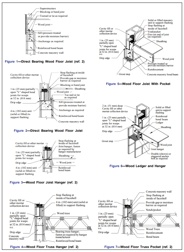
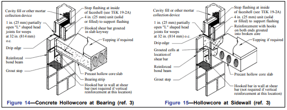
Direct Bearing Connection – The direct bearing connection is often the simplest type of connection. This connection is used at the top of concrete masonry walls or when a change in wall thickness provides a ledge with sufficient bearing area as shown in Figure 1.
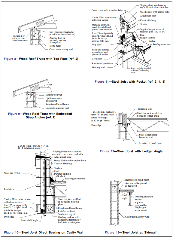
- Pocket Connection – A pocket connection consists of framing the floor or roof system into a void in the masonry wall. This detail is used when masonry continues above (either as part of the wall or as a parapet) the connection location and eccentricity is to be minimized. Care must be taken to insure that the use of a pocket does not interfere with the continuity of the vertical reinforcement in the wall.
- Hanger Connection – When it is desired to maintain the continuity of the wall for structural, aesthetic, or construction reasons, a wall hanger can be used to suspend the roof or floor system. Hangers are generally anchored to a wall through a joint and into a bond beam. However, hangers approved for direct attachment to the surface of a masonry wall are also available.
- Ledger Connection – As with hangers, ledger connection minimize the impact on the continuity of a masonry wall. A ledger connection reduces the necessary pre-planning and does not unduly impact the mason’s work as opposed to a pocket connection; thereby reducing the number of field modifications.
Note: Most of the connections herein depict flashing for water penetration resistance which should be used in all exterior walls. Normally flashing is not provided in interior walls.
FLOOR AND ROOFING SYSTEMS
Several materials are common to roof and floor construction. Wood, concrete, and steel are among the most frequently used framing materials in these applications.
Wood Systems
Wood framed floors and roofs are common in residential and low-rise construction. It is imperative when constructing a woodframed system that it not be in direct contact with the concrete masonry. Wood in contact with masonry materials may absorb moisture present in the concrete masonry causing the wood to rot. To prevent the resulting unwanted decay, the lumber used should be pressure-treated, naturally decay resistant, or have a moisture barrier placed between the wood and the concrete masonry.
Steel Systems
Steel-framed roofs using steel bar joints are very common in commercial structures because they are capable of spanning long distances. Steel bar joists typically use pocketed or ledger connections to concrete masonry walls. Proprietary systems that use concrete masonry units as a filler between the steel joists are also available.
Concrete Systems
Concrete slabs can take many forms, including pre-stressed, precast, and cast-in-place construction. Depending upon the size and number of stories associated with a given project, one concrete framing system may have unique benefits over another. For example, hollow core prestressed slabs can be erected quickly, without the need for formwork or shoring. Where sufficient space is available at the job site, precast slabs can be formed in stacks on-site, starting with the roof slab and using the top surface of the lower slab as the form for the next slab. Once cured, the precast slabs are lifted to their final location. The use of cast-in-place concrete floors and roofs, because of the time needed for forming, pouring, finishing, and curing, requires a building plan which is large enough to permit the masonry work to progress in one part of the structure while the floor in another area is completed.
REFERENCES
- Annotated Design and Construction Details for Concrete
Masonry, CMU-MAN-001-03, Concrete Masonry and
Hardscapes Association, 2003. - Concrete Masonry Homes: Recommended Practices. U.S
Department of Housing and Urban Development, Office of
Policy Development and Research, 1999. - Design for Dry Single-Wythe Concrete Masonry Walls,
19-02B, Concrete Masonry and Hardscapes Association,
2012. - Flashing Details for Concrete Masonry Walls, TEK 19-
05A, Concrete Masonry and Hardscapes Association,
2008. - Generic Wall Design for Single-Wythe Loadbearing Walls.
Masonry Institute of Michigan, 2000.