INTRODUCTION
Metal buildings are used extensively for warehouses and other structures requiring large, open floor spaces. Part of their design flexibility comes from the ability to clad metal buildings with a variety of materials to provide different appearances or functions to the buildings. Concrete masonry walls are popular enclosure systems for metal buildings because of masonry’s aesthetic appeal, impact resistance, strength, and fire resistance. The durability of concrete masonry resists incidental impacts from hand carts and forklifts, provides maximum protection in disasters such as earthquakes and hurricanes, as well as superior security, fire resistance, and noise control.
Concrete masonry walls used for metal buildings can include: exterior full-height walls, either with or without a parapet; exterior partial-height or wainscot walls; and interior loadbearing walls or nonloadbearing walls or partitions. Architectural concrete masonry units, such as colored, split faced, burnished, or scored units, can be used to provide an almost limitless array of textures and patterns to the walls. These units can be used for the entire facade or for banding courses to achieve specific patterns or highlight certain design aspects of the building.
A more detailed discussion of the system, along with structural design and construction considerations, is included in Concrete Masonry Walls for Metal Building Systems (ref. 1). The manual is intended to
bridge the gap between the engineer who designs the metal building system and the engineer who designs the concrete masonry walls to unify their respective knowledge.
DETAILS
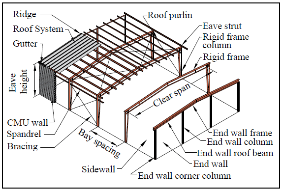
A typical metal building clad with masonry is shown in Figure 1. Figures 2 – 6 show some typical details used for exterior concrete masonry cladding on a metal building. These details may need to be modified to meet individual design conditions.
Because of the inherent material differences between steel and masonry, careful consideration must be given to accommodating differential movement between the two materials and their assemblies. In Serviceability Design Considerations for Low-Rise Buildings (ref. 2), a lateral drift limit of H/100 for a ten year recurrence wind loading based on main wind force resisting system loads is suggested for low rise buildings with exterior masonry walls reinforced vertically. See Table 12.12.1 of ASCE 7 (ref. 3) for the allowable story drift for seismic loading. Most reinforced masonry walls for metal buildings are designed to span vertically, supported by a steel spandrel at the top and by the foundation at the bottom.
WALL BASE
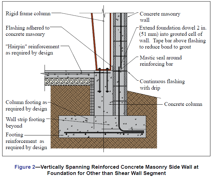
Because of stiffness and deformation incompatibilities between flexible steel and rigid masonry assemblies, and consequently to control the location of cracking in the masonry walls that may result from relatively larger steel frame deflections at the top of the structure, a “hinge” can be incorporated at the base of the masonry assembly to allow out-of-plane rotation.
Two such hinge connections are shown in Figures 2 and 3. The construction shown in Figure 2 uses through-wall flashing to break the bond at the base of the wall providing a simply supported condition allowing shear transfer but no moment for out-of-plane loading. In many cases the shear force can be adequately transferred by friction through the flashed bed joint. However, it is recommended that a positive shear connection be provided by extending foundation dowels across the joint. It is recommended that the number of bars extended across the horizontal joint be minimized, and that the extension be limited to 2 in. (51 mm), to ensure that the joint will behave as assumed. Therefore, every vertical bar otherwise required for strength at critical sections does not necessarily need to be extended through the joint.
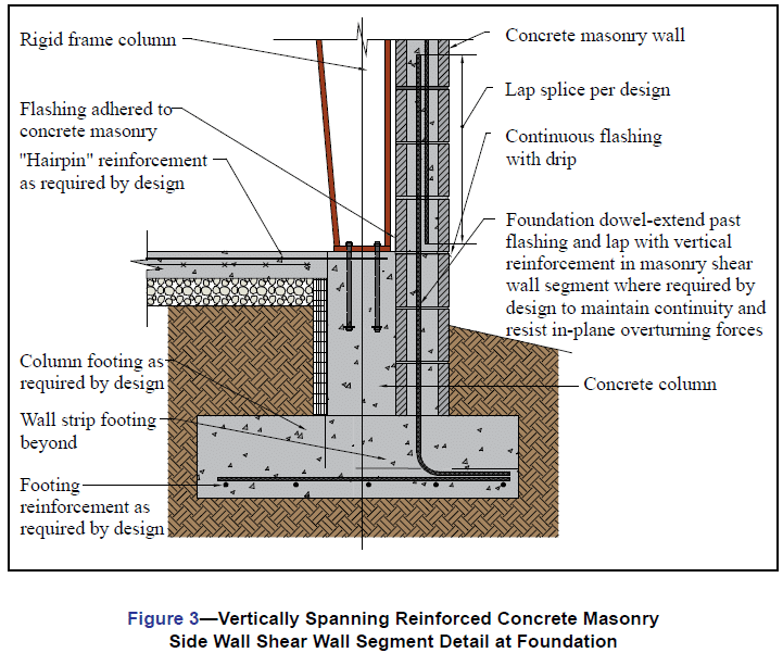
Masonry shear walls are very strong and stiff and are often used to resist lateral loads. However, masonry wall sections used as shear wall segments must have vertical reinforcement continuous into the foundation as shown in Figure 3. Flashing is also incorporated at the floor level to allow the wall some out-of-plane rotation due to building drift. Design aids are included in Concrete Masonry Walls for Metal
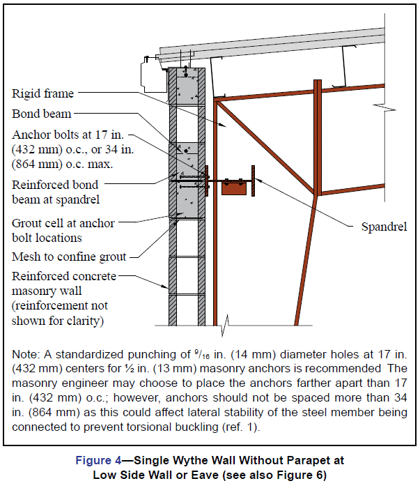
Building Systems (ref. 1) for inplane and out-of-plane reinforced masonry walls as well as for lintels and anchor bolts. Appendix C also presents design examples. As shown in Figure 4, these walls normally span vertically and are laterally supported by a spandrel at the top of the masonry portion of the wall.
When the masonry is designed with a base hinge, it is important to properly detail the building corners to accommodate the movements.
A vertical isolation joint should be placed near the building corner and proper consideration should be given to the masonry and steel connections at corner columns. Flexible anchors and/or slotted connections should be used.
WAINSCOT WALLS
Although full height masonry walls provide the most benefit particularly when the masonry is used for shear walls, partial-height walls, or wainscots, are sometimes used. These walls are commonly 4 to 10 ft (1.2 to 3.0 m) high with metal panel walls extending from the top of the masonry to the roof. The masonry provides strength and
impact resistance for the portion of the wall most susceptible to damage.
COLUMN DETAIL
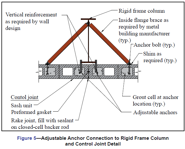
Figure 5 shows the connection of a rigid frame column to concrete masonry sidewalls with a coincident vertical control joint. The details show vertically adjustable column anchors connecting the wall to the column. For walls designed to span vertically, it is good practice to provide a nominal number of anchors connecting the wall to the column to add stiffness and strength to the edge of the wall. If rigid enough, these anchors can assist in laterally bracing the outside column flange. For larger lateral loads, more substantial connections may be required. Anchorage to end wall columns is very similar.
SPANDREL DETAIL
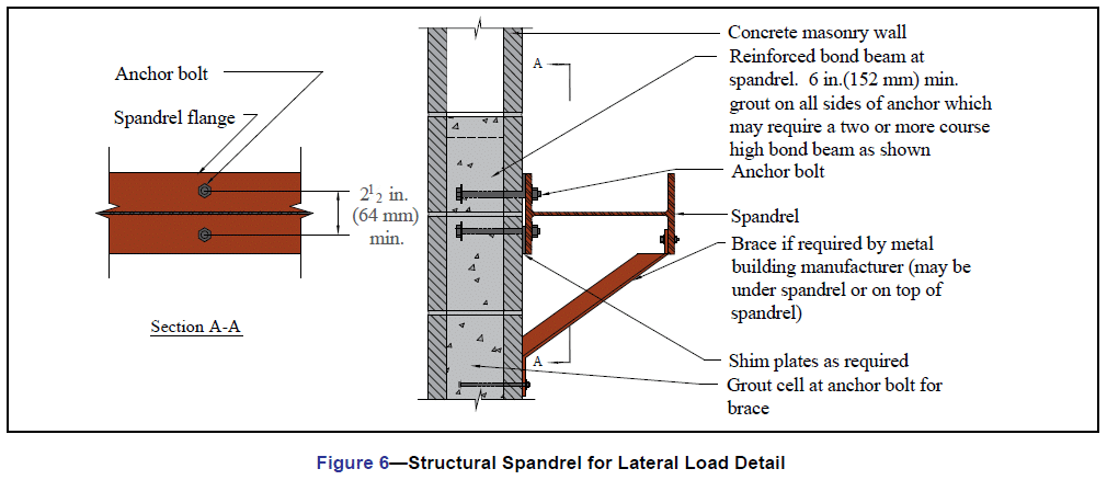
A typical spandrel detail is shown in Figure Spandrels should be placed as high as possible to reduce the masonry span above the spandrel, especially on walls with parapets. Depending on the rigid frame configuration used, rigid frame connection plates and diagonal stiffeners may restrict the spandrel location. The spandrel is designed by the metal building manufacturer. If the inner flange of the spandrel needs to be braced, the metal building manufacturer will show on the drawings where the braces are required along with the information needed for the masonry engineer to design them and their anchorage to the wall.
Shim plates should be used at spandrel/masonry connections to allow for camber in the spandrel and other construction tolerances (see Figure 6). The steel spandrel should never be pulled to the masonry wall by tightening the anchor bolts.
CONSTRUCTION SEQUENCE
Typically, construction of metal buildings with concrete masonry walls proceeds as follows: concrete footing and column placement; concrete masonry foundation wall construction to grade; concrete slab placement; steel erection; and concrete masonry wall construction. Note, however, that this sequence may need to be modified to meet the needs of a particular project. For example, this construction sequence changes when loadbearing end walls are used. In this case, the steel supported by the masonry is erected after the masonry wall is in place.
Coordination between the various trades is essential for efficient construction. Preconstruction conferences are an excellent way for contractors and subcontractors to coordinate construction scheduling and to avoid conflicts and delays.
REFERENCES
- Concrete Masonry Walls for Metal Building Systems, CMU-MAN-003-11. Concrete Masonry & Hardscapes Association, Metal Building Manufacturers Association, International Code Council, 2011.
- Serviceability Design Considerations for Steel Buildings, AISC Steel Design Guide #3. American Institute of Steel Construction, 2003.
- Minimum Design Loads for Buildings and Other Structures, ASCE 7-05. American Society for Civil Engineers, 2005.