
INTRODUCTION
Concrete masonry screen walls are used in every part of every country on the globe, on every conceivable style of building, and for a wide variety of purposes. Created originally as a functional building element, the screen wall combines privacy with observation, interior light with shade and solar heat reduction, and airy comfort with wind control for both interior and exterior applications. Curtain walls, fences, sun screens, and room dividers are just a few of the limitless applications for a concrete masonry screen wall. The scope of this TEK focuses on the design and detailing of non-loadbearing concrete masonry screen walls. For loadbearing screen wall applications, users are referred to the applicable engineering analysis provisions of TMS 402 (Ref. 5).
Extra attention to the design of screen walls is warranted because of the relatively high percentage of open area in their face. The open area is created usually by the use of special screen units with decorative openings in their face. Screen walls should be designed to resist wind pressure and seismic forces to which they are exposed to while providing a durable and attractive architectural finish. Strength and stability is provided by: (1) incorporating steel reinforcement (either conventional reinforcing bars, bed joint reinforcement, and/or anchors); (2) limiting the clear span of screen walls; and/or (3) providing a separate support system capable of carrying lateral loads from the assembly to the backup support(s).
MATERIALS
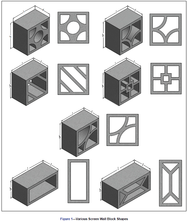
Screen Wall Units – Due to the virtually limitless number of shapes and sizes for concrete masonry screen wall units, designers are encouraged to check on the availability of any specific shape during the early planning stages of a project. Some shapes are available only in certain localities and others may be restricted by patent or copyright. Figure 1 illustrates a general overview of some of the shapes that may be encountered for screen wall design. Note that these unit configurations can come in various thicknesses depending upon availability.
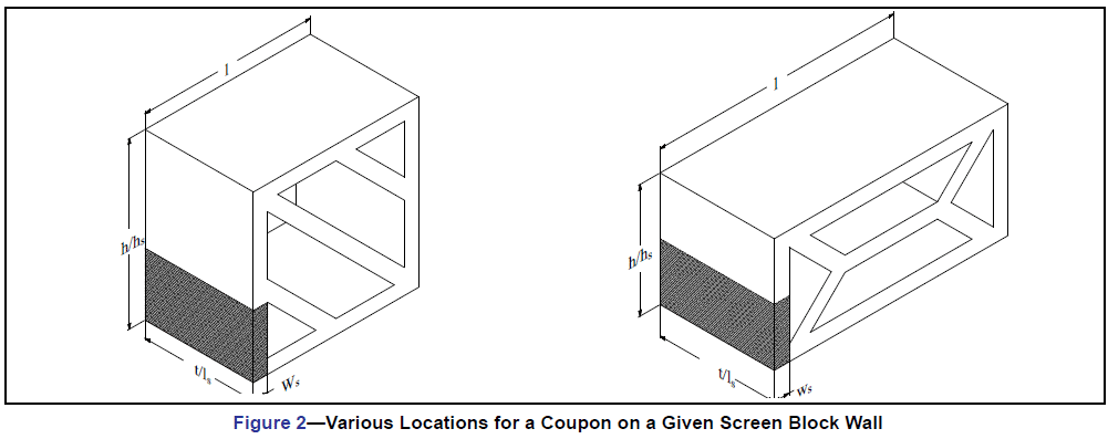
Despite screen wall units being used predominately in onloadbearing applications, they still should be of high quality for their intended construction. At a minimum, concrete masonry units used for screen walls should meet the requirements of ASTM C90, Standard Specification for Loadbearing Concrete Masonry (Ref. 1). Verification of unit properties should be in accordance with ASTM C140, Standard Test Methods for Sampling and Testing Concrete Masonry Units and Related Units, Annex A1 (Ref. 2). Due to their unique configuration full-size testing of screen wall block is not feasible, thus requiring that coupons be removed from the screen wall block for compressive strength testing. The coupon must meet the specimen size requirements of a height to thickness ratio equal to two (2) to one (1) and a length to thickness ratio equal to four (4) to one (1). In some situations, the length requirement for a specimen may not be able to be attained. In these cases, the length should be greater than or equal to the height of the specimen.
When tested in accordance with ASTM C140, screen units must attain a minimum average net area compressive strength of 2000 psi (13.7 MPa) based on three units tested. In addition to the above compressive strength requirements, the recommended minimum thickness of any part of the screen wall unit should not be less than 3/4 inches (19 mm).
Figure 2 presents a visual representation of where the coupon for a given screen block wall unit can be extracted. Per ASTM C140, the height of the coupon must be in the same orientation as the height of the screen block when it is placed.
Further information on ASTM C90, ASTM C140, and concrete masonry units can be found in CMU-TEC-001-23 (Ref. 7), TEK 18 01D (Ref. 16), and TEK 18-02C (Ref. 17).
Mortar – ASTM C270, Standard Specification for Mortar for Unit Masonry (Ref. 3), contains non-mandatory recommendations for the type of mortar to use for various applications. Type N mortar is the recommended type for exterior and interior nonloadbearing walls, which would encompass screen walls.
Alternatives such as Type S or M mortar can be used where the design variable or exposure conditions warrant.
For additional information on mortar, see TEK 09-01A (Ref. 9).
Grout – Grout for embedding steel reinforcement in horizontal or vertical cells should comply with ASTM C476, Standard Specification for Grout for Masonry (Ref. 4).
For additional information on grout, see TEK 09-04A (Ref. 10) and TEK 18-08A (Ref. 9).
Reinforcement and Anchor – Reinforcing steel comes in three different forms for screen walls: 1) Steel wire reinforcement that is prefabricated consisting of cold-drawn wire, 2) reinforcing bars, and 3) anchors. During the design, the designer must be cognizant of the cover and protective coating requirements for the steel. These requirements are largely dependent on the type of weather the screen wall will encounter during the life of the assembly and these requirements may affect the design of the wall.
For additional information on reinforcement steel, see TEK 12-01B (Ref. 12), TEK 12-02B (Ref. 13), TEK 12-04D (Ref. 14), and TEK 12-
06A (Ref. 15).
DESIGN
The design of a screen block wall depends upon a number of factors: function, location (exterior or interior), aesthetic requirements, and provisions of local building codes. They are used extensively for the following types of construction: (1) interior partitions, (2) free-standing walls supported on their own foundations, (3) and enclosed panels in masonry walls or external frames.
Screen wall partitions are designed as non-loadbearing panels with primary consideration given to adequate anchorage at panel ends and/or top edge, depending upon the type of lateral support furnished. Free-standing walls include such assemblies as fences and other exterior non-loadbearing screens that receive lateral stability from a structural frame braced to an adjacent structure or designed as a cantilever from the foundation.
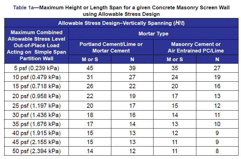
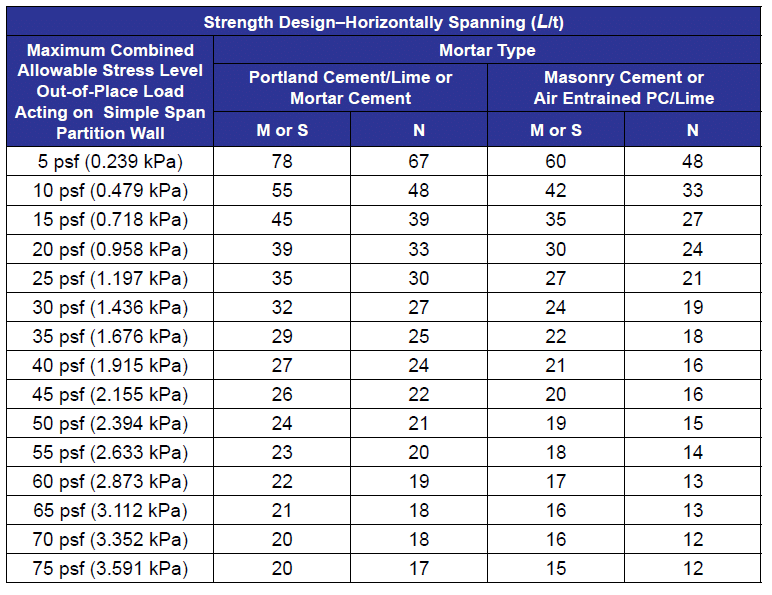
Non-loadbearing screen walls should have a minimum nominal thickness of 4 in. (102 mm). Based on the nominal thickness of the unit and design method to be used, Table 1 was derived to determine the maximum height or length that can be built for a screen wall that has its units placed on a full mortar bed. This chart has been broken down into four separate distinct design categories: (1) Vertically Spanning per Allowable Stress Design (ASD) method, (2) Horizontally Spanning per Allowable Stress Design (ASD) method, (3) Vertically Spanning per Strength Design method, and (4) Horizontally Spanning per Strength Design method.
The use of Table 1 requires the following:
1) The tables assume the wall is either vertically spanning (supported at the top and bottom of the wall) or horizontally spanning and laid in a running bond (supported at the sides of the wall). If the wall is to be horizontally spanning using a bond pattern other than running bond, then the table is not valid and cannot be used.
2) The table assumes the screen wall units are placed on a full mortar bed with no open spaces between units.
3) The wind pressure and seismicity pressure expected to be encountered for the wall must be known.
4) The design pressure can be from either seismic or wind out-of place loading.
5) The screen walls are not designed to carry axial loads other than their own weight and are not part of the lateral force resisting system (shear walls).
Wind and seismic loads are typically the most frequently encountered external force that will interact with the wall. Wind pressures are calculated using the provisions ASCE 7, Minimum Design Loads for Buildings and Other Structures (Ref. 6) for open signs or lattice structures thus taking into account the open area of the screen wall. Seismic forces are also determined in accordance with ASCE 7 for architectural components based upon the installed weight of the screen wall. Based on the calculated loads, the designer should use the higher of the two loads to determine the maximum height to thickness or length to thickness ratio for a given design method.
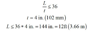
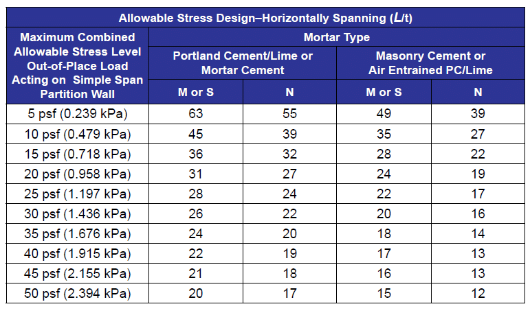
For example, when building a horizontally spanning screen block wall with nominal 4 in. (102 mm) thick units placed with Type S portland cement mortar in an area that encounters 15 psf (0.718 kPa) wind pressure, the maximum length span of the screen wall is 12 ft (3.66 m) using the ASD method. Determined as follows:
Per Table 1a for a horizontally spanning wall,
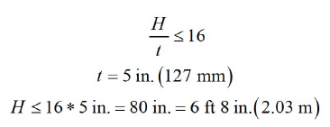
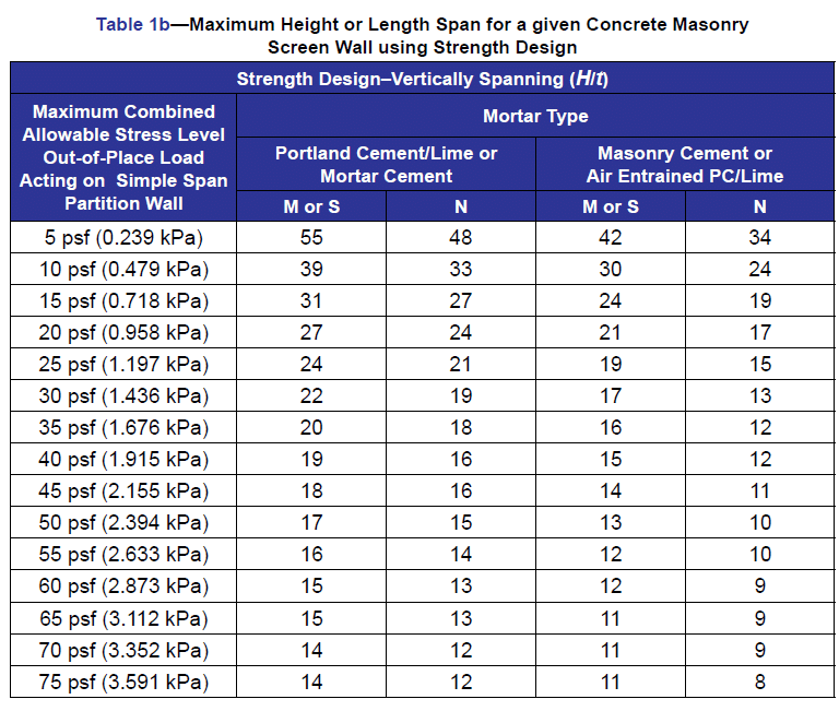
Another example, when building a vertically spanning screen block wall with nominal 5 in. (127 mm) thick units placed with Type N portland cement mortar in an area that encounters 40 psf (1.915 kPa) wind pressure, the maximum height span of the screen wall is 6 ft 8 in. (2.03 m) using the Strength Design method. Determined as follows:
Per Table 1b for a vertically spanning wall,
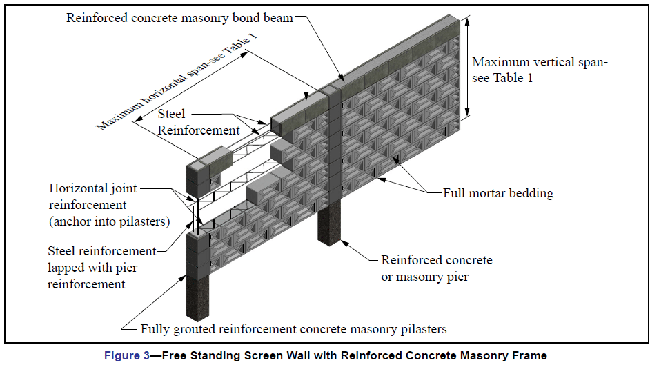
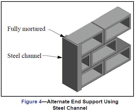
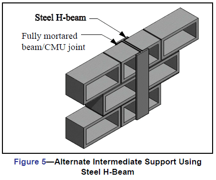
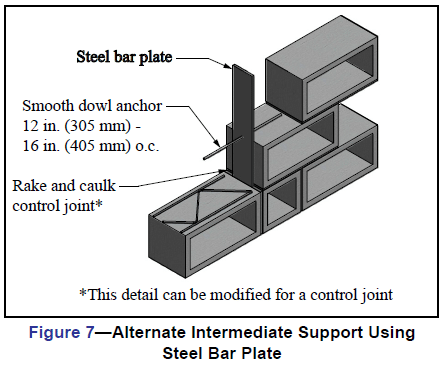
Adequate anchorage should be provided between screen walls and lateral supports, and the supports should be designed to transfer loads to the structure and into the ground. Examples of anchorage of free-standing screens to their supporting framework is accomplished by various means as illustrated in Figure 3, with alternate support conditions shown in Figures 4, 5, 6, and 7. Lateral support may be obtained from cross walls, piers, columns, posts, or buttresses for horizontal spans, and from floors, foundations, roofs, or spandrel beams for screen walls spanning the vertical direction. Consideration should be given to expansion caused by temperature change and by deflection under load when screen wall panels are enclosed in a structural framing system.
CRACK CONTROL
The use of steel reinforcement is permitted where it can be embedded in mortar joints, in bond beam courses, or grouted into continuous vertical cells. Horizontal bed joint reinforcement consisting of two No. 9 gauge wires or equivalent, placed 16 inches o.c. is recommended when screen wall units are laid in stack bond. Horizontal bed joint reinforcement is not required for running bond masonry; however, the use of it helps with crack control in a masonry wall.
Ladder-type joint reinforcement and truss-type bed joint reinforcement are both acceptable forms of joint reinforcement as the reinforcement will lie on a solid face and not interfere with vertical reinforcement.
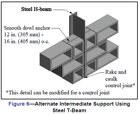
Control joints can be used at the discretion of the designer to mitigate cracking potential. Figures 6 and 7 illustrate options for supporting screen walls while incorporating control joints. For more information on crack control see, CMU-TEC-009-23 (Ref. 11).
REFERENCES
- Standard Specification for Loadbearing Concrete Masonry
Units, ASTM C90-15. ASTM International, Inc., 2015. - Standard Test Methods for Sampling and Testing Concrete
Masonry Units and Related Units, ASTM C140-15. ASTM
International, Inc., 2015. - Standard Specification for Mortar for Unit Masonry, ASTM
C270-14a. ASTM International, Inc., 2014. - Standard Specification for Grout for Masonry, ASTM
C476-10. ASTM International, Inc., 2010. - Building Code Requirements for Masonry Structures, TMS
- The Masonry Society, 2016.
- Minimum Design Loads and Associated Criteria for
Buildings and Other Structures, ASCE 7. American Society
of Civil Engineers, 2016. - Concrete Masonry Unit Shapes, Sizes, Properties, and
Specifications, CMU-TEC-001-23, Concrete Masonry &
Hardscapes Association, 2023. - Grout Quality Assurance, TEK 18-08B, Concrete Masonry
& Hardscapes Association, 2005. - Mortars for Concrete Masonry, TEK 09-01A, Concrete
Masonry & Hardscapes Association, 2004. - Grout for Concrete Masonry, TEK 09-04A, Concrete
Masonry & Hardscapes Association, 2005. - Crack Control Strategies for Concrete Masonry
Construction, CMU-TEC-009-23, Concrete Masonry &
Hardscapes Association, 2023. - Anchors and Ties for Masonry, TEK 12-01B, Concrete
Masonry & Hardscapes Association, 2011. - Joint Reinforcement for Concrete Masonry, TEK 12-02B,
Concrete Masonry & Hardscapes Association, 2005. - Steel Reinforcement for Concrete Masonry, TEK 12-04D,
Concrete Masonry & Hardscapes Association, 2006. - Splices, Development & Standard Hooks for Concrete
Masonry Based on the 2009 & 2012 IBC, TEK 12-06A,
Concrete Masonry & Hardscapes Association, 2013. - Evaluating the Compressive Strength of Concrete
Masonry, TEK 18-01D, Concrete Masonry & Hardscapes
Association, 2017. - Sampling and Testing Concrete Masonry Units, TEK 18-
02C, Concrete Masonry & Hardscapes Association, 2014.