INTRODUCTION
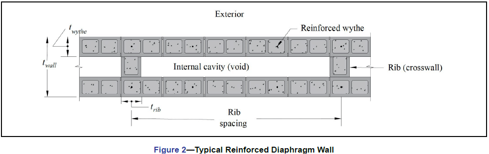
Diaphragm walls are composed of two wythes of masonry with a large cavity or void. The wythes are bonded together with masonry ribs or crosswalls in such a way that, structurally, the wythes function compositely—as though the entire thickness is effectively solid.
Figure 1 shows a stone-clad university building with reinforced concrete masonry diaphragm walls, used to recreate the campus’ Gothic architecture. The use of reinforced diaphragm walls allowed support of the tall sidewalls and gable ends.
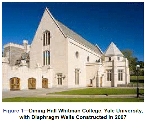
Figure 2 shows a cross-section of a typical diaphragm wall. The reinforced wythes can be fully or partially grouted. The exterior face can be constructed with a weathering face, like a conventional single wythe wall, or finished with a veneer. The voids can be used for placement of utilities and/or insulation.
This TEK discusses construction considerations for diaphragm walls: TEK 14-24, Design of Reinforced Concrete Masonry Diaphragm Walls, (ref. 1) covers the structural design.
CONSTRUCTION ADVANTAGES
Reinforced diaphragm walls present several construction benefits. These include:
- As shown in Figure 1, thick walls can be created efficiently using standard units bonded together. Thicker walls can be used to create taller walls.
- The wall can have exposed finished surfaces both inside and out. In addition, those finishes can be different because they are created by two different masonry wythes and can, therefore, feature different unit types/sizes/colors.
- The wall construction proceeds very much as conventional single wythe or cavity wall construction.
- The exterior wythe can be constructed with a veneer.
- The large interior voids allow for easy placement of utilities and/or insulation.
KEY CONSTRUCTION FEATURES
Construction Sequence
The construction sequence for diaphragm walls can vary based upon how the ribs are interconnected with the two wythes. Building Code Requirements for Masonry Structures (ref. 2), referred to as TMS 402, Section 5.1.1.2.5 provides three methods for connecting intersecting walls to allow shear transfer:
- At least fifty percent of the masonry units at the interface must interlock. This means the ribs could be constructed in running bond with every other course interlocking with the wythes. Thus, the wythes and the ribs would be constructed concurrently.
- Walls must be anchored by steel connectors grouted into the wall and meeting the following requirements: (a) Minimum size: 1/4 in. x 1-1/2 in. x 28 in. (6.4 x 38.1 x 711 mm) including 2-in. (50.8-mm) long, 90-degree bend at each end to form a U or Z-shape. (b) Maximum spacing: 48 in. (1,219 mm). Thus, it is possible to build the ribs separately from the wythes, which provides significant flexibility in construction.
- Intersecting reinforced bond beams must be provided at a maximum spacing of 48 in. (1,219 mm) on center. The area of reinforcement in each bond beam must be not less than 0.1 in.2 per ft (211 mm2/m) multiplied by the vertical spacing of the bond beams in feet (meters). Reinforcement must be developed on each side of the intersection.
Again, this provides flexibility in sequencing the wall construction. However, the grouting must be done simultaneously with the wythe construction.
Masonry Bond
TMS 402 Section 5.1.1.2.1 requires that the masonry at intersecting walls be laid in running bond for composite action between wythes to be effective. This requirement controls the entire construction of a diaphragm wall and mandates running bond for both the wythes and the ribs.
Reinforcement
Vertical reinforcement is typically placed in the cells of the wythes as is done in single-wythe construction. Posttensioning can be placed either in the cells of the wythes or within the void itself. If placed within the void and laterally restrained tendons are specified, tendon restraints must be fabricated. TEK 03-14, Post-Tensioned Concrete Masonry Wall Construction (ref. 3) provides a more detailed overview. Depending on the project’s seismic and/or loading requirements, horizontal reinforcement can be placed in either grouted bond beams or in the bed joints of the wythes and ribs. Horizontal bond beams are beneficial in that they can also serve as the interlock between the ribs and wythes, as well as shear reinforcement for the ribs.
Ribs (Crosswalls)
The structural design will determine whether or not the ribs require vertical reinforcement. The interlock with the wythes transfers shear forces across the intersections, and the vertical reinforcement in the wythes acts as the total wall reinforcement.
Wall Grouting
The requirement for full or partial wall grouting is a design decision. Any cells or bond beams with reinforcement must be grouted. The need for additional grouting is determined based on the design requirements. Both low-lift and high-lift grouting techniques are suitable to diaphragm walls. See TEK 03-02A, Grouting Concrete Masonry Walls, (ref. 4) for more detailed information.
Water Management
Strategies for water penetration resistance of conventional masonry walls depend on whether the wall is singlewythe or a cavity wall. Water penetration resistance for the exterior wythe of a diaphragm wall follows the strategies employed for single wythe construction. If the exterior wythe has a veneer and cavity, it is flashed and weeped the same way as a single wythe masonry cavity wall. With no veneer and cavity, the exterior wythe of a diaphragm wall is flashed and weeped the same way as a similarly constructed partially grouted single wythe wall. Flashing and weeps are not necessary if the exterior wythe is solid grouted.
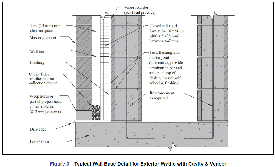
Figure 3 shows a typical wall base detail for a diaphragm wall with an exterior veneer and cavity. The cavity between the exterior diaphragm wythe may contain insulation and an air/moisture barrier, as required. The veneer is anchored to the exterior wythe of the diaphragm wall and is weeped and flashed. TEK 19-05A, Flashing Details for Concrete Masonry Walls, (ref. 6) provides additional details applicable to this construction.
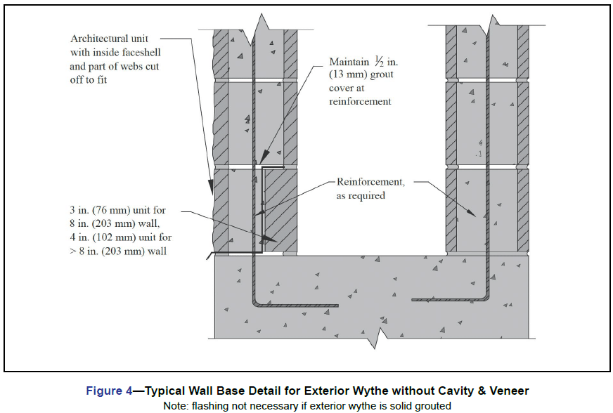
Figure 4 shows a wall base detail applicable to an exterior diaphragm wythe without a cavity and veneer. TEK 19-02B, Design for Dry Single Wythe Concrete Masonry Walls, (ref. 7) provides additional details for single wythe construction.
Openings through diaphragm walls, roof/floor intersections, etc. are also flashed and weeped similar to conventional concrete masonry walls.
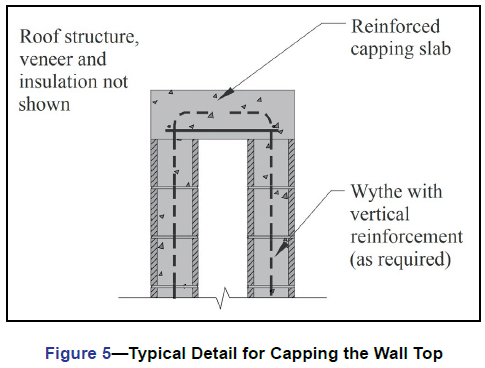
Top of the Wall
Diaphragm walls require closure at the top to transfer vertical loads and close off the void. Figure 5 shows one common detail for capping the walls. The cast-in-place capping slab at the top takes the place of what would normally be bond beams in single-wythe walls. For post tensioned walls, the top slab provides a convenient anchorage point for the tendons.
Utilities and Insulation
The voids offer several opportunities not common in masonry walls. They provide chases for duct work and utilities with minimal cutting of the units and allow for additional insulation if desired. Diaphragm walls can be insulated on the exterior, by using a veneer and insulated cavity, or by using an exterior insulation system. They can also be insulated on the interior, using furring, insulation and gypsum wallboard. When insulation is placed in the voids, however, the ribs produce a large thermal bridge, reducing the effectiveness of the insulation. 06-11A, Insulating Concrete Masonry Walls, (ref. 5) provides more detailed information.
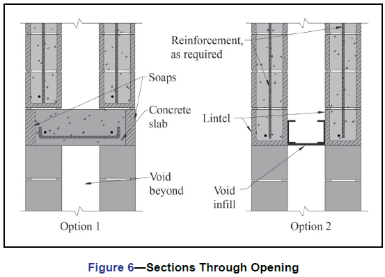
Openings
Constructing openings in diaphragm walls is also very similar to single-wythe walls (see Figure 6). The entire void should be spanned/filled at the opening and the exterior wythe flashed above (as appropriate), as shown in Figure 4. Figure 6 Option 1 shows a reinforced concrete slab that has been designed as a header for the opening. Figure 6 Option 2 has lintels to support the wythes over the opening. The void at the headers and sills is infilled with a nonmasonry material, such as exterior gypsum sheathing. The jambs should be infilled with masonry wherever they don’t already align with the ribs. Note that Figure 6 does not show flashing that may be necessary.
Control Joints
Control joints are provided in concrete masonry walls to control cracking primarily from movement due to shrinkage and thermal effects. In diaphragm walls, the ribs will tend to restrict some of that movement, however, because there is currently no research to quantify these effects, current practice is to place control joints at intervals based upon CMU-TEC-009-23, Crack Control Strategies for Concrete Masonry Construction, (ref. 8). TEK 14-24 discusses these criteria and provides an example for determining control joint spacing for a diaphragm wall.
Although the inner wythe will generally be exposed principally to shrinkage with only minor thermal effects, it is common to place control joints in the same locations and to provide similar shrinkage reinforcement in both wythes.
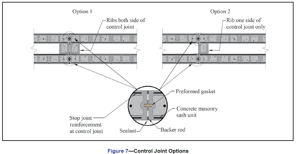
Figure 7 shows two methods of creating control joints in a diaphragm wall. Option 1, with ribs on both sides of the control joint, does a better job keeping water out of the void than Option 2 because a failure of the sealant would allow water to penetrate between the ribs, rather than into the void itself. The control joints in both wythes should be sealed for water protection.
CMU-TEC-009-23 contains additional control joint constructions/details that can also be used on diaphragm walls, including fire-rated joints and control joints that allow shear transfer.
SUMMARY
Diaphragm walls provide several beneficial features and are applicable to a wide variety of projects. Constructing reinforced concrete masonry diaphragm walls uses methods and techniques commonly known to most masons. The added thickness of the wall provides some variations in the overall reinforcement and layout concepts but the techniques are typical for masonry.
REFERENCES
- Design of Reinforced Concrete Masonry Diaphragm Walls, TEK 14-24. Concrete Masonry & Hardscapes Association, 2014.
- Building Code Requirements for Masonry Structures, TMS 402-16, Reported by The Masonry Society 2016.
- Post-Tensioned Concrete Masonry Wall Construction, TEK 03-14. Concrete Masonry & Hardscapes Association, 2002.
- Grouting Concrete Masonry Walls, TEK 03-2A. Concrete Masonry & Hardscapes Association, 2005.
- Insulating Concrete Masonry Walls, TEK 06-11A. Concrete Masonry & Hardscapes Association, 2010.
- Flashing Details for Concrete Masonry Walls, TEK 19-05A.
Concrete Masonry & Hardscapes Association, 2008. - Design for Dry Single Wythe Concrete Masonry Walls, TEK 19-02B. Concrete Masonry & Hardscapes Association, 2012.
- Crack Control Strategies for Concrete Masonry Construction, CMU-TEC-009-23, Concrete Masonry & Hardscapes Association, 2023.