
INTRODUCTION
Concrete masonry is an extremely versatile building product in part because of the wide variety of aesthetic effects that can be achieved using concrete masonry units. Concrete masonry units are manufactured in different sizes, shapes, colors, and textures to achieve a number of finishes and functions. In addition, because of its modular nature, different concrete masonry units can be combined within the same wall to produce variations in texture, pattern, and color.
For the purposes of this TEK, “standard” concrete masonry units are considered to be two-core units (i.e., those with three cross webs), 8 in. (203 mm) high, 16 in. (406 mm) long and 4, 6, 8, 10 or 12 in. (102, 154, 203, 254 or 305 mm) wide. In addition, concrete brick is available in typical lengths of 8, 9, 12 and 16 in. (203, 229, 305 and 406 mm), nominal 4 in. (102 mm) width, and a wide range of heights.
In addition to these “standard” units, many additional units have been developed for a variety of specific purposes, such as aesthetics, ease of construction and improved thermal or acoustic performance. For the purposes of this TEK, units other than those described above as standard will be referred to as specialty units. Specialty units can include units of different sizes or different unit configurations. Units of specialty configuration which are used at discreet wall locations rather than to construct an entire wall, such as sash units, pilaster units, etc. are not discussed here, nor are proprietary units discussed in detail. See CMHA CMU-TEC-001-23 Concrete Masonry Unit Shapes, Sizes, Properties, and Specifications (ref. 1), for information on these units.
By definition, specialty units are not available from all concrete masonry manufacturers. In some cases, such as the A- and H-shaped units used for reinforced construction, the “specialty” is commonly available in certain geographic areas. In California, for example, A- and H-shaped units are considered to be standard units. Other unit configurations discussed below may be available across the country, but from a relatively small number of producers. For this reason, it is imperative that the designer communicate with local concrete masonry manufacturers to establish the availability of the units discussed in this TEK, as well as other specialty units that may be available. Local manufacturers can provide detailed information on specific products, or the feasibility of producing custom units.
Regardless of unit size or configuration, concrete masonry units are required to comply with Standard Specification for Loadbearing Concrete Masonry Units, ASTM C90 (ref. 2). See CMHA CMU-TEC-001-23, ASTM Specifications for Concrete Masonry Units (ref. 3), for more detailed information.
This TEK discusses the advantages of using specialty units, and some of the design and construction issues that may impact the use of these units
SPECIALTY UNIT SIZES
Concrete masonry units may be produced with widths, heights, and/or lengths other than the standard sizes listed above. Use of these units produces walls with a scale and aesthetic properties different from those built with standard-sized units. Construction productivity may be impacted by the size, weight and configuration of the units selected. Also, some of the special shapes and sizes may not be available, and may require modification on site by the contractor.
One of the most important construction consideration when using specialty-sized units is modular coordination. Modular coordination is the practice of laying out and dimensioning structures and elements to standard lengths and heights to accommodate proportioning and incorporating modular-sized building materials. Modular coordination helps maximize construction efficiency and economy by minimizing the number of units that must be cut to accommodate window and door openings, for example. See CMHA TEK 05-12, Modular Layout of Concrete Masonry (ref. 4) for information on modular coordination with standard-sized units.
In addition to the specialty height units and specialty length units discussed below, veneer units (typically 4 in. (102 mm) thick) may be available in various specialty sizes, up to 16 in. high by 24 in. long (406 x 610 mm).
Specialty Unit Heights
Although the most commonly available concrete masonry unit height is 8 in. (203 mm), concrete masonry units may be available in 4-in. (“half-high”) or 12-in. (102- and 305-mm) high units. Half-high units are gaining in popularity. They provide an aspect ratio similar to brick, but are hollow loadbearing units. See CMHA TEK 05-15, Details for Half-High Concrete Masonry Units (ref. 7) for more detailed information.
As long as the unit cross-section (i.e., face shell and web thicknesses) is the same as the corresponding 8-in. (203-mm) high unit, these specialty height units can be considered to be structurally equivalent to their corresponding 8-in. (203-mm) high unit.
Vertical modular coordination must be adjusted in some cases with these units. Using 4-in. (102-mm) high units provides some additional flexibility in placing wall openings, as the wall is built on a 4-in. (102-mm) vertical module rather than an 8-in. (203-mm) vertical module. With 12-in. high units, the wall height, door opening height and window opening height should ideally be a multiple of 12-in. (305-mm) to minimize cutting units on site (see Figure 1). Note that special door frames may need to be ordered to fit the masonry opening. See CMHA TEK 05-12 for further information.
Veneer anchor spacing requirements remain the same regardless of unit height. For units with a height greater than 8 in. (203 mm), these spacing requirements should be verified and the anchor spacing planned out prior to construction. As an example, consider 12-in. (305-mm) high veneer units installed over a concrete masonry backup wythe. The anchor spacing requirements are: maximum wall surface area supported of 2.67 ft2 (0.25 m2); maximum vertical anchor spacing of 18 in. (457 mm); and maximum horizontal anchor spacing or 32 in. (813 mm) (ref. 11). In this case, anchors need to be installed in every course to meet the requirement for a maximum vertical anchor spacing of 18 in. (457 mm). If the anchors are spaced horizontally at the maximum 32 in. (813 mm), the wall area supported is 2.67 ft2 (0.25 m2), so this veneer anchor spacing meets the code requirements. Veneer anchor spacing requirements are presented in detail in CMHA TEK 03-6C, Concrete Masonry Veneers (ref. 8).
Another consideration for units with a height exceeding 8 in. (203 mm) is the use of joint reinforcement. Joint reinforcement in concrete masonry can be used to provide crack control, horizontal reinforcement in low seismic categories, and bond for multiple wythes, corners and intersections. Most requirements and rules of thumb for joint reinforcement are based on a specific area of reinforcement per foot of wall height and assume an 8-in. (203-mm) modular unit height. These should be considered prior to construction for units with heights exceeding 8 in. (203 mm). For example, empirical concrete masonry crack control criteria calls for horizontal reinforcement of at least 0.025 in.2/ ft of wall height (52.9 mm2/m) between control joints. This corresponds to a maximum vertical spacing of 16 in. (406 mm) when 2-wire W1.7 (9 gage, MW11) joint reinforcement is used. When using 12-in. (305-mm) high units, the joint reinforcement of that size needs to be placed in every horizontal bed joint to meet this requirement. A better alternative is to use 2-wire W2.8 (3/16 in., MW18) joint reinforcement, with a maximum vertical spacing of 24 in. (610 mm), allowing the joint reinforcement to be placed every other course when using 12-in. (305-mm) high units. See CMHA CMU-TEC-009-23, Crack Control Strategies for Concrete Masonry Construction (ref. 6) for a discussion of joint reinforcement for crack control, and TEK 12-02B, Joint Reinforcement for Concrete Masonry (ref. 7), for an overview of code requirements for the use of joint reinforcement. Properties of wire for masonry (including steel cross-sectional area) can be found in Table 3 of CMHA TEK 12-04D, Steel Reinforcement for Concrete Masonry (ref. 8)

Specialty Unit Lengths
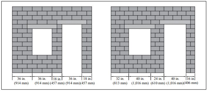
Specialty concrete masonry unit lengths include 18-in. and 24-in. (457- and 610-mm) long units. Concrete masonry units longer than 16 in. (406 mm) are produced with the same equivalent web thickness (i.e., the average web thickness per length of wall) as 16-in. (406-mm) long units, per ASTM C90. As such, these units can be considered to be structurally equivalent to a 16-in. (305-mm) long unit of the same width.
Horizontal modular coordination should be considered when using these units. For example, wall length and placement of wall openings should ideally be a multiple of the unit length, as shown in Figure 2.
Veneer anchor spacing and joint reinforcement considerations are the same as for standard-length units.
Specialty Unit Widths
In addition to the standard unit widths of 4, 6, 8, 10, and 12 in. (102, 152, 203, 254, 305 mm), specialty widths may include 14 and 16 in. (356 and 406 mm). Because unit width does not affect modular coordination, layout considerations are generally the same as for walls constructed using standard concrete masonry units.
One construction issue that arises with different unit widths is corner details. CMHA TEK 05-09A, Concrete Masonry Corner Details (ref. 9), presents details to minimize cutting of units while maintaining modularity for 4, 6, 8, 10, and 12 in. (102, 152, 203, 254, 305 mm) wide units. Corner details for 14-in. (356-mm) wide units are similar to those for 12-in. (305 mm) wide units, using 8-in. (203-mm) wide units with 2 x 6 in. (51 x 152 mm) pieces of masonry to fill the gaps in the inside corners. Because 16 in. (406 mm) is a modular size, corner details for these units are similar to those for 8-in. (203-mm) wide units. A standard 8-in. (203-mm) wide unit is used in each course at the corner to maintain the running bond.
Structural considerations may differ, however, as both the section properties and wall weight varies with wall width. CMHA Tech Note CMU-TEC-002-23, Weights and Section Properties of Concrete Masonry Assemblies, (ref. 10) list these properties for 14 and 16 in. (356 and 406 mm) wide walls.
From a construction standpoint, the larger cores of 14- and 16-in. (356 and 406 mm) wide units accommodate more reinforcement or insulation, when used, and require more grout to fill reinforced cells.
SPECIALTY UNIT CONFIGURATIONS
Specialty unit configuration refers to units whose cross-section varies significantly from that of a standard two-core concrete masonry unit. In this case, structural properties may be different from standard units. Modular coordination is the same as for standard units, unless the specialty configuration is also produced in a specialty size.
A variety of concrete masonry units have been developed to address specific performance or construction criteria. For example, units developed for improved energy efficiency may have reduced web areas to reduce heat loss through the webs, a thickened interior face shell for increased thermal storage, and/or additional cavities within the unit to accommodate insulation. Acoustical concrete masonry units provide increased sound absorption and/or diffusion.
These units may have unique construction and/or structural considerations, depending on their configuration. The concrete masonry producer should be contacted for more detailed information on the specific unit under consideration.
Units to Facilitate Reinforced Construction
Concrete masonry unit shapes have been developed for a wide variety of applications. The shapes illustrated in Figure 3 have been developed specifically to accommodate vertical reinforcement. Bond beam and lintel units have also been developed to accommodate horizontal reinforcement.
Open-ended units allow concrete masonry units to be inserted around vertical reinforcing bars. This eliminates the need to lift units over the top of embedded vertical reinforcement, or to thread the reinforcement through the masonry cores after the wall is constructed.
Because all open cells of A- and H-shaped units are grouted and bond beam and lintel units are fully grouted, walls constructed with these units can use the same structural design parameters as for grouted standard units.

REFERENCES
- CMHA CMU-TEC-001-23, Concrete Masonry Unit Shapes, Sizes, Properties, and Specifications, Concrete Masonry & Hardscapes Association, 2023.
- Standard Specification for Loadbearing Concrete Masonry Units, ASTM C90-09. ASTM International, 2009.
- Modular Layout of Concrete Masonry, CMHA TEK 05-12. Concrete Masonry & Hardscapes Association, 2008.
- Details for Half-High Concrete Masonry Units, CMHA TEK 05-15. Concrete Masonry & Hardscapes Association,
- Concrete Masonry Veneers, CMHA TEK 03-6C. Concrete Masonry & Hardscapes Association, 2012.
- Crack Control Strategies for Concrete Masonry Construction, CMHA CMU-TEC-009-23, Concrete Masonry and Hardscapes Association, 2023.
- Joint Reinforcement for Concrete Masonry, CMHA TEK 12-02B. Concrete Masonry & Hardscapes Association,
- Steel Reinforcement for Concrete Masonry, CMHA TEK 12-04D. Concrete Masonry & Hardscapes Association,
- Concrete Masonry Corner Details, CMHA TEK 05-09A. Concrete Masonry & Hardscapes Association, 2004.
- Weights and Section Properties of Concrete Masonry Assemblies, CMU-TEC-002-23. Concrete Masonry & Hardscapes Association, 2023.
- Building Code Requirements for Masonry Structures, TMS 402-08/ACI 530-08/ASCE 5-08. Reported by the Masonry Standards Joint Committee, 2008.