Revised 2022
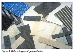
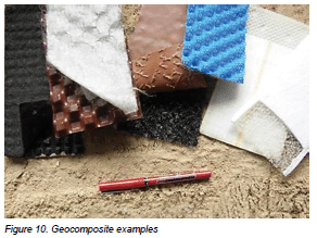
This Tech Note provides fundamental information on geosynthetics including a brief history, uses, and basic applications for interlocking concrete pavements (ICP) and permeable interlocking concrete pavements (PICP). While this Tech Note provides some general guidelines on engineered applications, it is not intended to provide geosynthetic engineering design advice. While many of the general principles and applications of geosynthetics are easily understood, the field of geosynthetics and the technical information available is too voluminous for a single technical bulletin. This Tech Note is presented as an introduction to the wide range of geosynthetic materials available, as shown in Figure 1, for readers interested in this subject and its application to segmental concrete pavements.
The term geosynthetics derives its meaning from Greek word “geo” meaning of the earth or ground, and the synthetic referring to materials formed through a chemical process by human action rather than by nature. The term geosynthetic is defined in ASTM D4439 Standard Terminology for Geosynthetics (ASTM 2015) as “a planar product manufactured from polymeric material used with soil, rock and earth or other geotechnical engineering related material as an integral part of a man-made project, structure, or system.” Geosynthetics are predominantly manufactured from polymers and may also include fiberglass, rubber, or other natural materials.
HISTORY
Various materials have been placed on or in soils under pavements for thousands of years. Compacted stones were used in roadway construction in Roman days to stabilize roadway soils and their edges. Natural fibers and fabrics were later mixed with soil to improve road quality, particularly when built on unstable soil. Such materials were also used to stabilize steep slopes and walls such as ancient ziggurats. While many of the earliest attempts to improve or reinforce soil were not recorded, there is some evidence. Some of the oldest roads in Britain utilized split logs, or a ‘corduroy’ road, laid over peat bogs to provide a stable platform. There is also evidence that in some cases a stabilized soil mixed with paving stones or paving blocks were placed over the corduroy road.
Obviously, natural materials in soils led to biodegradation from microorganisms. The advent of polymers in the mid-twentieth century provided longer lasting and more stable materials for pavements.
Even before the term geosynthetics existed, synthetic materials were being used in the field. In the early 1960s, the Dutch used geotextiles in the design of the Delta Works flood protection project as a response to deadly North Sea flooding there in 1953. The terms “geotextile” and “geosynthetics” were introduced by Dr. J.P. Giroud in a Paris engineering conference in 1977 (Kelsey 2014). Compared to other paving materials, geosynthetics have a short history of about 50 years, even though improving the load bearing capacity and strength of soil has been occurring for thousands of years.
TYPES OF GEOSYNTHETICS
Geosynthetics can be grouped in several product categories, i.e. geotextiles, geogrids, geomembranes, geonets, geosynthetic clay liners, geopipes, geofoam, geocells and geocomposites. Polymer materials make them suitable for use in applications where high durability is required. They can also be used in exposed, above ground applications. With their range of materials and products, this enables geosynthetics to have a wide range of applications in many civil, geotechnical, transportation, geo-environmental, hydraulic, and private development applications. These include roads, airfields, railroads, embankments, retaining structures, reservoirs, canals, dams, erosion control, sediment control, landfill liners, landfill covers, mining, aquaculture and agriculture.
Geotextiles
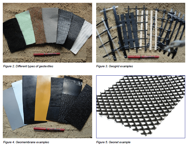
Geotextiles form one of the two largest groups of geosynthetics. They are fabrics consisting of synthetic fibers predominantly made of polypropylene (PP) rather than natural fibers making them less susceptible to biodegradation. Synthetic fibers are made into flexible, porous sheets, made by standard weaving machinery, are called slit film, monofilament or multifilament. Another subset of geotextiles are matted together randomly and not woven. These nonwoven materials are made with processes called needle punched or heat bonded. There is also a very small subset of geotextiles that are knitted. Examples are shown in Figure 2.
Geotextiles are permeable to liquids and gases, but vary to a wide degree. These variations produce materials with a wide range of mechanical and hydraulic properties. As a result, there are at least 100 specific application areas for geotextiles. However, these can be simplified to four discrete functions: separation, reinforcement, filtration, and/or drainage.
Geogrids
Rather than being a continuous fabric, geogrids are polymers formed into an open, small grid-like configurations with apertures between individual ribs as illustrated in Figure 3. Geogrids typically consist of polyethylene (PE), polypropylene (PP), or polyester (PET). They are typically classified as being bidirectional, with equal strength in both directions, or unidirectional, with a greater strength in one direction. Geogrids are made by one of three methods; (1) stretching a polymer sheet in one, two or three directions for improved physical properties (2) woven or knit using standard textile manufacturing methods; or (3) laser or ultrasonically bonded rods or straps. While there are many applications, geogrids function almost exclusively as reinforcement.
Geomembranes
Geomembranes represent the largest group of geosynthetics, and see higher sales than geotextiles. Geomembranes grew rapidly in the United States and Germany when government regulations in the early 1980s required lining of solid waste landfills. Uses expanded to all types of landfills, surface impoundments, canals, and containment of vapors, liquid or solid materials. Geomembranes are typically made from polyvinyl chloride (PVC), ethylene propylene diene monomer (EPDM), high-density polyethylene (HDPE) and linear lower density polyethylene (LLDPE) as shown in Figure 4. The range of applications extend beyond environmental management to geotechnical and transportation uses, including roles in hydraulic designs.
Geonets
Geonets, also called geospacers by some, are formed by a continuous extrusion of parallel sets of polymeric ribs at acute angles to one another. See Figure 5. When the ribs are opened, relatively large apertures are formed into a netlike configuration. Two types are most common, either bi-planar or tri-planar designs. Many different types of drainage cores are available consisting of nubbed, dimpled or cuspated polymer sheets, three-dimensional networks of stiff polymer fibers in different configurations and small drainage pipes or spacers within geotextiles. In most cases their surfaces are covered with a geotextile as a component in a geocomposite. The typical polymer is polypropylene (PP). They function by providing planar or lateral movement of liquids (or gasses) and are also called drainage mats. CMHA Tech Note PAV-TEC-014–Concrete Paving Units for Roof Decks covers the use of drainage mats in detail. Use of geonets under segmental pavement must be done so with caution. Geonets can compress significantly or even collapse under heavier loads. This compression, if significant, can lead to movement in the segmental pavement elements leading to breakage, joint or bedding sand loss and eventual failure of the system.
Geosynthetic clay liners
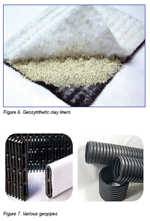
Geosynthetic clay liners (GCLs) sandwich a thin layer of bentonite clay between two geotextiles or bonded to a geomembrane as shown in Figure 6. Structural integrity of the composite is obtained by needle-punching, stitching or adhesive bonding. GCLs are used as a component beneath a geomembrane or alone in containment, hydraulic, transportation and geotechnical applications. GCLs are a competitive alternative to compacted clay liners.
Geopipe
Geopipe is another name for drainage pipe and is manufactured from high-density polyethylene (HDPE) and polyvinylchloride (PVC) as shown in Figure 7. Versions are available with rigid, smooth walls or flexible corrugated pipe. The geopipes may be perforated to allow liquids or gases to enter or exit the pipe as well as non-perforated to transfer them. There has been enormous growth in the use of corrugated HDPE and large diameter pipe in recent years.
Geofoam
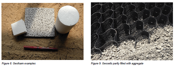
Geofoam is created by a polymer expansion of polystyrene (EPS) resulting in a “foam” consisting of many closed, gas-filled, cells as shown in Figure 8. The skeletal nature of the cell walls is the unexpanded polymer material. The resulting product is generally in the form of large, but extremely light, blocks which are stacked side-by-side providing lightweight fill in numerous applications. Geofoam is also used for insulation of frost- sensitive soil applications. In some areas, geofoam is being used as a substitute for compacted dense-graded aggregate base in mostly residential, pedestrian-only applications. This new application requires further research and evaluation of field performance on various soils and climates.
Geocells
Geocells (also known as cellular confinement systems) are three-dimensional honeycombed structures that confine compacted soil or base materials within them as shown in Figure 9. Extruded polymer strips ultrasonically welded together in series are expanded on site form stiff walls (typically textured and perforated) that create a three-dimensional cellular mattress. Infilled with soil or base materials, a more stable structure is created. The cellular confinement reduces the lateral movement of materials, thereby maintaining compaction and stiffness capable of distributing loads over a wide area. Traditionally used in slope protection and earth retention applications, geocells are increasingly used for long- term road and railroad support. Much larger geocells are also made from stiff geotextiles sewn into similar, but larger, unit cells that are used for protection bunkers and walls. Geocells have been used on a limited basis to strengthen open-graded aggregate bases used in PICP systems. This new application is being evaluated in full-scale test.
Geocomposites
A geocomposite combines geotextiles, geogrids, geonets and/ or geomembranes in a factory fabricated unit as shown in Figure 10. GCLs are an example of a geocomposite as are geonets covered with geotextile. Applications are numerous and constantly growing and cover the range of functions for geosynthetics.
HANDLING GEOSYNTHETICS
Many geosynthetics are supplied in rolls with unique serial numbers for manufacturer quality control. Installation contractors should remove these labels from delivered materials and keep them with other project records.
Geosynthetics will degrade when exposed to ultra-violet rays in sunlight over long time periods so they should remain in their packaging, covered, or stored inside until use. While additives are in the polymers that provide some resistance, continued exposure weakens them and they may not perform as expected. Excessive heat can also damage geosynthetics which provides another reason to store geotextiles away from sunlight in places with air circulation. On a hot sunny day, placing a heavy tarp over geosynthetics rolls can heat it and reduce strength and performance. To maintain their performance, geotextiles are best stored elevated above the ground in their original packaging out of direct sunlight, protected from precipitation and excessive heat. Further information is available in ASTM D4873 Standard Guide for Identification Storage & Handling of Geotextiles.
GEOSYNTHETIC FUNCTIONS
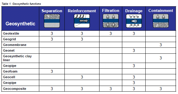
Geosynthetics are generally selected and designed for a particular application by considering their primary function or functions. Table 1 illustrates functions of various geosynthetics. The functions are defined below.
Seperation
Separation places a flexible geosynthetic material such as a permeable geotextile between dissimilar materials so the integrity and function of both materials remain intact or even be improved. Paved roads, unpaved roads, and railroad bases are common applications. Also, the use of thick nonwoven geotextiles for cushioning and protection of geomembranes is in this function category. In addition, for most applications of geofoam and geocells, separation is the major function.

Reinforcement
Reinforcement synergistically improves a system’s strength when introduced to a geotextile, geogrid or geocell all of which function well in tension. These can strengthen a soil that is otherwise weak in tension.

Applications include mechanically stabilized and retained earth walls and steep soil slopes. Such walls can be connected to concrete units to create vertical retaining walls. Other applications are reinforcement of weak soils and over deep foundations for embankments with heavy surface loads. Unlike geotextiles, stiff polymer geogrids and geocells do not have to be in tension to provide soil reinforcement. Stiff two-dimensional geogrids and three-dimensional geocells interlock with the aggregate particles, providing reinforcement through confinement of the aggregate. The resulting mechanically stabilized aggregate layer provides improved loadbearing performance. Stiff polymer geogrids with very open apertures in addition to three-dimensional geocells made from various polymers are increasingly specified in unpaved and paved roadways, within dense and open-graded aggregate bases, and especially in railroad ballast where the improved loadbearing characteristics can significantly reduce the need for highquality, expensive imported aggregate.
Filtration
Filtration allows water or gases to move through the plane of the material without the undesired movement or loss of soil. Filtration applications are highway underdrain systems, retaining wall drainage, landfill leachate collection systems, silt fences and curtains, and flexible forms for bags, tubes and containers.

Drainage
Drainage allows water or gases to move within the plane of the material without the undesired movement or soil loss. Geopipe highlights this function, and also geonets, geocomposites, and very thick geotextiles. Drainage applications for these different geosynthetics are retaining walls, sport fields, dams, canals, reservoirs, and capillary breaks. Sheet, edge and wick drains are geocomposites for various soil and rock drainage applications.

Containment
Containment is achieved with geomembranes, geosynthetic clay liners, or some geocomposites which function as liquid or gas barriers. Landfill liners and covers rely on their continued containment. All hydraulic applications (tunnels, dams, canals, surface impoundments, and floating covers) use these geosynthetics as well.

USE OF GEOTEXTILES
Typical pavement applications achieve separation, filtration and possibly reinforcement. Geotextiles can help provide a longer service life and reduce pavement material use. Understanding geotextile properties is fundamental to selecting them for pavement applications. Properties are listed below and each are associated with an ASTM test method.
- Grab tensile strength
- Wide width tensile strength
- Trapezoidal tear strength
- CBR puncture
- UV resistance
- Apparent opening size
- Permittivity
- Flow Rate
- Transmissivity
While there is a broad range of geotextiles properties, some are more appropriately applied for a given application. In general, the grab tensile strength and wide width tensile strength tests provide the ultimate strength and strain values at specified elongation rates. Trapezoidal tear and CBR puncture characterize resistance to installation damage. The CBR puncture test measures the force required to push a 2 in. (50 mm) piston through a geotextile similar to a 2 in. (50 mm) rock interaction with a geotextile in the field. Permittivity, flow rate, and transmissivity are hydraulic properties on how readily water moves through or within a given geotextile.
Geotextile Properties
Geotextiles are classified into two main categories based on their method of manufacture: woven and non-woven.
Woven geotextiles
Woven geotextiles are manufactured from various polymers with increasing strengths typically increasing their cost. Woven geotextiles typically provide good resistance to abrasion from bedding materials and bases. They also provide strength with minimal elongation (stretching) because of the orientation of the individual fibers. This allows woven geotextiles to function as a good reinforcement. Woven geotextiles are classified into subcategories based on the shape of the fibers used to construct them.
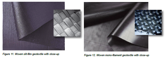
Woven Slit-film—Also known as woven slit-tape geotextile, this fabric is made from long, continuous wide fiber relative to their thickness. See Figure 11. When woven together the fibers create very small openings that impede water movement to a slow rate while preventing the passage of fine soil particles. The weave creates lower filtration and greater separation, as well as being a relatively economical material. The fabric is for applications where separation with some reinforcement and lower water filtration volumes are required.
Woven mono-filament—This weave is constructed using similar techniques to slit-film geotextiles but with round or oval individual fibers resulting in a tight, stable geotextile. See Figure 12. This creates larger holes and a higher water flow through it. Because of the higher fiber cost and specialized machinery used to weave it, mono-filament geotextiles are typically the most expensive woven geotextiles.
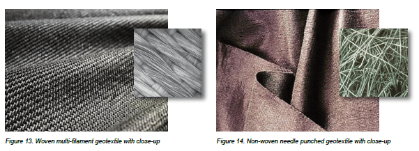
Woven multi-filament—These are manufactured using bundles of fibers that opens up the weave so more water can pass compared to a slit-film geotextile. See Figure 13. The multi- filament fiber material cost is also lower than a monofilament fiber. When compared to a slit-film or mono-filament geotextiles, multi-filament geotextiles provide filtration at a rate and cost between them.
Nonwoven Geotextiles
The other main category of geotextiles is nonwoven where the fibers are laid out randomly and run through one of two secondary processes called needle-punching or heat bonding to give the material its structure.
Nonwoven needle-punched is created by pushing needles with barbs at their tips through the mass of random fibers. See Figure 14. This process forces some of the fibers through the matrix which binds the fibers together. This creates a material with many small openings through the mass of fibers that allow water to flow a high rate while filtering the water. The mass also creates loft or thickness that allows water to travel laterally within the plane of the geotextile which provides drainage. Some nonwoven needle-punched geotextiles are thicker which increases their drainage capacity. Unfortunately, the random fiber mat gives needle-punched geotextile a relatively low strength. When a heavy load is applied, the fabric can stretch significantly before it tears. For some applications its ability to stretch or elongate is a desirable feature.
The thickness of a nonwoven needle punched geotextile is identified by the weight per unit area. For example, a 4 ounce per square yard is considered a typical, lightweight material approximately 2 mm thick. Whereas a 20 oz/sy would be a very thick material probably over 10 mm. Thick needle-punched geotextiles are used for demanding applications like landfill sites and the material can be expensive. Nonwoven needle-punched geotextiles are sometimes used to provide a separation layer for a geomembrane to prevent punctures from aggregates during compaction or from other objects.
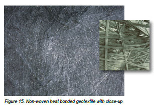
Nonwoven heat bonded geotextiles are created using polymer fibers with a high melt temperature in their core encapsulated by a second polymer with a lower melt temperature. See Figure 15. The fibers are laid out in a random layer and then run through heated rollers, called calendaring, that melts the outer layer of the fibers and presses them together. Heat bonded geotextiles have higher strength compared to non- woven needle-punched fabrics because the individual fibers are welded together. However compressing the fibers together reduces the openings in the matrix and this restricts water flow and its filtration function. The compressed matrix minimizes its ability for water to flow within the layer and provide drainage. Table 2 summarizes functions and relative cost for the different types of geotextiles presented.

Basic Design Concepts for Geotextiles
The American Association of State Highway and Transportation Officials (AASHTO) M-288 Standard Specification for Geotextile Specification for Highway Applications is a widely accepted geotextile specification by provincial and state departments of transportation as well as municipalities. M-288 covers six geotextile applications: subsurface drainage, separation, stabilization, permanent erosion control, sediment control, and fabrics used within paving materials. M-288 is not a design guideline and places design and selection decisions on the engineer who considers site-specific soil and water conditions.
M-288 includes three survivability classes for geotextiles, i.e. Class 1, 2 and 3. Class 1 is the most severe and Class 3 represents least severe site conditions. Potential damage during construction and use is considered in selecting a class. Each class subdivides geotextiles according to elongation, greater or less than 50%, and the designer can select nonwoven or woven geotextiles for each class based on various characteristics listed in Table 2. For stabilization and separation applications, a woven fabric is typically less expensive than nonwoven options. For subsurface drainage and erosion control, woven fabrics are more expensive than non-woven.
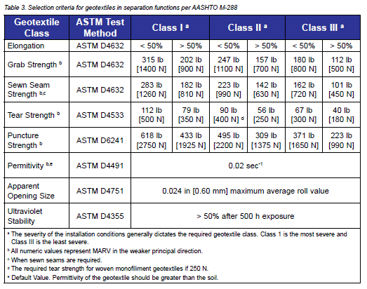
When selecting a geotextile primarily for its separation function, it is important to make sure that it exceeds these minimum criteria specified in M-288 as shown in Table 3, also provided in CMHA PAV-TEC-002–Construction of Interlocking Concrete Pavements.
AASHTO M-288 also provides guidance on the overlapping of geotextile pieces necessary to achieve continuous coverage as shown in Table 4, also provided in CMHA Tech Note PAV- TEC-002.
In March 2012, the AASHTO National Transportation Product Evaluation Program (NTPEP) approved the adoption of a work plan for the evaluation of geotextile materials in highway applications. NTPEP is an AASHTO program that evaluates materials and products of common interest for use in highway and bridge construction. The program provides cost-effective evaluations for state DOTs by eliminating duplication of testing and auditing by the states, and duplication of effort by the manufacturers that provide products for evaluation. The NTPEP work plan establishes a list of manufacturing facilities, private label companies, geotextile converters and their associated geotextile products that conform to the quality control and product testing requirements of the work plan and AASHTO M-288. This provides a resource on companies that can provide geotextiles that conform to AASHTO M-288. Visit www.ntpep. org for additional information.
Geotextile Applications for Segmental Concrete Pavements
The following provides examples of where geotextiles might be used in segmental concrete pavements. Recommendations are provided on the type of geotextiles best suited to site conditions. While these are general guidelines, contractors should follow the recommendations and use materials specified in the construction documents.
When placing geotextile avoid wrinkles in the fabric. Follow the overlap recommendations specified in ASSHTO M-288 as noted in Table 4 above and avoid excessive overlapping of edges. Make sure the geotextile is placed in full contact with the surrounding soils or aggregates. Voids, hollows or cavities from wrinkles created under or beside the geotextile compromises its intended function.

Figure 16 illustrates geotextiles separating the compacted aggregate base from the soil subgrade. This can help maintain consolidation of the base materials over time by preventing intrusion of fines in the bottom and sides. This slows the rate of rutting in the base and on the soil subgrade.
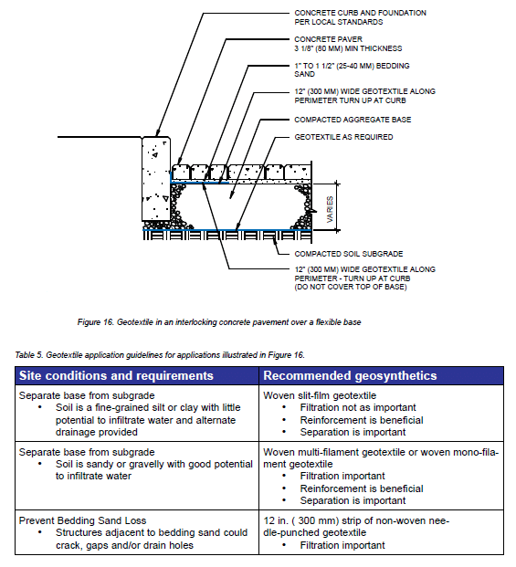
Geotextile placed under the bedding sand next to the curb provides a ‘flashing’ function. This separates the sand from the base and prevents sand loss into joints between the concrete curb and the compacted aggregate base, as they are two structures that can move independently of each other. Table 5 provides guidelines for geotextile selection depending on conditions and requirements.
Figure 17 illustrates geotextile on a concrete base in a crosswalk applications. For new sidewalks, crosswalks, and streets, 12 in. (300 mm) wide strips of geotextile are recommended over all joints in new concrete bases to prevent loss of bedding sand, as well as over weep holes. New asphalt generally should not require geotextile on it except at curbs, structures and pavement junctions where bedding sand might enter. For existing asphalt and concrete bases, the surface of each should be inspected for cracks, and their severity and extent determined for repairs. If cracks are few and minor (suggesting substantial remaining life in these bases), geotextile should be placed over the cracks to prevent potential future loss of bedding sand. Table 6 provides guidelines for geotextile selection for overlay applications depending on the conditions and requirements.
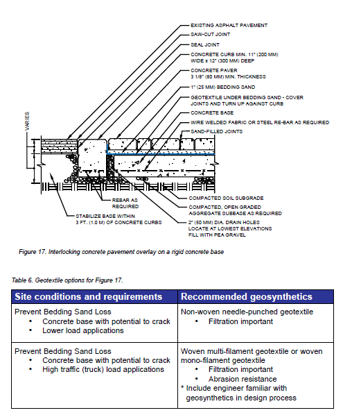
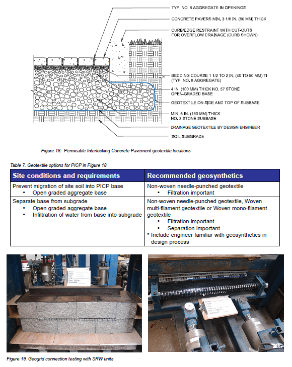
Figure 18 illustrates a typical application of geotextile in PICP. Its application against the sides of the subbase against the excavated soil is essential in all PICP projects that do not use full-depth concrete curbs that completely confine open- graded aggregates at the pavement perimeter. The design and selection of geotextiles for PICP is covered in detail in the CMHA manual, Permeable Interlocking Concrete Pavements— Design, Specification, Construction, and Maintenance. Table 7 provides recommendation for the selection of a geosynthetic in PICP applications based on the conditions and requirements.
USE OF GEOGRIDS
Geogrids typically reinforce applications such as mechanically stabilized earth (MSE) and weak soil subgrade improvement for roadway applications. Geogrid properties include the following:
- Wide width tensile strength
- Strain
- UV resistance
- Aperture size
- Coefficient of interaction
For MSE applications, long term design strength (LTDS) in pounds per foot or kilonewtons per meter is determined in the design process to represent the effective strength of the geogrid over the design life of the structure. Additional properties are evaluated and applied to determine the LTDS. These include creep, i.e. the amount of deformation under sustained load; durability, the resistance to degradation; and installation damage, or strength reduction that occurs during installation. Creep, durability, and installation damage factors are applied to the ultimate strength of the geogrid as reduction factors to determine the LTDS.

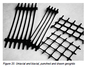
If the geogrids is to be used with a segmental retaining wall (SRW) system additional tests related to the connection strength and shear strength are performed as shown in Figure 19. The connection strength test determines the maximum load that can be applied to the connection between the SRW units and the geogrid. The shear strength test considers the reduction in shear strength between SRW courses with the geogrids inclusion.
Geogrid Properties
Geogrids are divided in to three categories: 1) punched and drawn, 2) woven or knitted and 3) bonded. These groupings are based on their manufacturing method. As mentioned above geogrids are also classified on their load carrying ability. If the geogrid is designed to carry load in one principal direction, typically along its length, it is referred to as a uniaxial geogrid. If the geogrid is designed to carry load along its length and width it is called biaxial.
Punched and Drawn Geogrids
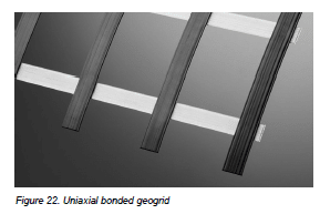
The first category of geogrid, punched and drawn, is a sheet of plastic with punched holes, heated and stretched in one or more directions. Uniaxial geogrids are stretched in one direction as shown in the two samples on the left of Figure 20. Biaxial geogrids are stretched in two or more directions as shown in the two samples on the right of Figure 20. Polymers typically are polypropylene (PP) or high density polyethylene (HDPE). This type of geogrid is stiff, allowing it to anchor in the soil to carry large loads with minimal movement.
Woven or Knitted Geogrids
The second category of geogrid is woven or knitted. The fibers are typically made from polyester with variations made from polyvinyl alcohol and fiberglass. Once the fibers are woven or knitted, they are coated with polyvinyl chloride (PVC) or similar materials to bind them together and increase durability. Uniaxial (shown on the left in Figure 21) and biaxial woven or knitted geogrids (right in Figure 21) are possible. The more fibers in one direction, the higher the strength. Woven and knitted geogrids tends to be more flexible which making them easier to manipulate on the jobsite.
Bonded Geogrids
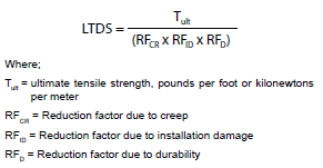
The third category of geogrid is bonded which represents a small portion of geogrids. Figure 22 show a geogrid made from polyester ribbons welded together ultrasonically to form a very stiff mat. Uniaxial and biaxial varieties are available.
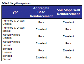
Biaxial geogrids are best suited to aggregate base reinforcement in pavement applications whereas uniaxial geogrid are optimized for MSE (soil subgrade) applications. However, biaxial geogrids may have some installation advantages when used in MSE applications. Table 8 compares geogrid types and applications. The cost of each geogrid depends on the strength required from the grid material.
Basic Design Concepts with Geogrids
When designing with a geogrid, the manufacturer can provide and ultimate strength of the material. However site conditions degrade the geogrid over its life due to loads within the pavement or wall structure. The designer must consider the effects of creep (i.e., slow elongation), installation damage and durability to determine a maximum allowable long term design strength (LTDS).
Creep occurs in polymer materials when subject to a sustained load over a long period of time. If the load is too great, the polymer will continually stretch and eventually break. The load must be limited to prevent this unrestricted creep. This is considered in the design as the RFCR factor. When aggregate is compacted on the geogrid it is damaged and the strength reduced. Different types of aggregates will create different amount of damage. This affect is considered in the strength calculation as the RFID factor. Lastly, chemical and biological agents may affect the geogrid over the life of the geogrid causing it to lose strength. These affects are considered in the strength equation by including the RFD factor. An experienced design engineer can apply appropriate reduction factors in estimating the LTDS.
Geogrid Applications with Segmental Concrete Pavements
Geogrids are designed to provide reinforcement, and can enhance the strength and longevity of interlocking concrete pavements. Some examples are presented below. Recommendations are also provided for the type of geogrid best suited to the site conditions. Nonetheless, contractors should always follow recommendations for materials specified in the construction documents.
When placing geogrids they should be installed with a small amount of tension. Wrinkles in the geotextile should be removed. When placing aggregate on top of a geogrid, spread it out so it will keep the tension the geogrid instead of releasing the tension, i.e. place the aggregate and spread it towards the free ends of the geogrid. For SRWs, do not overlap geogrid between block courses. This will push the units above the overlap out of horizontal alignment.
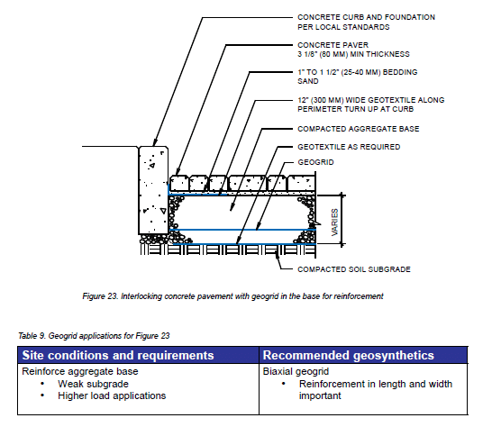
Figure 23 illustrates using a geogrid layer to improve the strength and load distribution characteristics of a compacted aggregate base. This method of construction would be appropriate for low strength soils. It is important to note that the geogrid will typically be placed within the aggregate base and not at the base – subgrade interface. This will optimize the reinforcement function of the geogrid. If a minimal level of containment is desirable, and a less than optimized reinforcement function is allowable the geogrid may be placed at the subgrade – base interface. Table 9 provides recommendations for geogrids used in base reinforcement applications depending on the conditions and requirements.
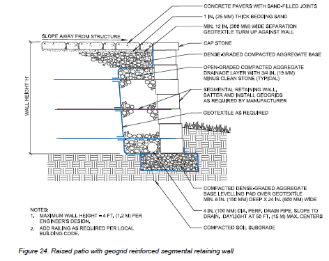
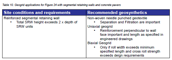
Figure 24 is a cross section detail of a raised patio. This application can benefit from reinforcement by using a geogrid to create a mechanically stabilized earth retaining wall. Additionally filtration is necessary to prevent fine soil particles from being washed out of the backfill and pavement base, which can lead to settlement over an extended period. Confinement of the aggregate used to construct the retaining wall base can also be advantageous when building over weaker fine grained soils like silts and clays. Table 10 provides recommendations for geotextiles and geogrids used in SRW applications depending on the conditions and requirements.
USE OF GEOMEMBRANES
Geomembranes create an impermeable barrier that prevents the flow of liquid or gas. Geomembranes are manufactured from polyvinyl chloride (PVC), ethylene propylene diene monomer (EPDM), high-density polyethylene (HDPE) and linear lower density polyethylene (LLDPE). Other polymers that may be used for special applications include chlorosulfonated polyethylene (CSPE), chlorinated polyethylene (CPE), polypropylene (PP), and very flexible polyethylene (VFPE). Each of these polymers is unique and provides varying levels of resistance to acids, alkalis or petrochemicals. Some polymers can also function in extreme heat or cold. Normally, the surface of a geomembrane is smooth, but some sloped applications can benefit from a textured surface that provides greater friction with the adjacent geotextiles or soil.
PICP systems can be designed and constructed to accommodate three drainage conditions:
- Full infiltration of water into to a high infiltration rate soil subgrade with no underdrains;
- Partial infiltration of water into a low infiltration rate soil subgrade with some outflow through underdrains; and
- No infiltration into a soil subgrade with all outflow exiting through underdrains.
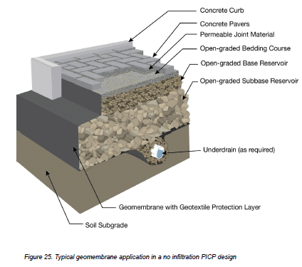
All conditions have similar surfacing, and base/subbase reservoir construction. In some PICP designs, a geomembrane is used next to building foundations or adjacent pavements with dense graded bases to prevent them from saturation and damage. Geomembranes may be used within a PICP subbase on sloped applications as check dams to slow the flow of water and encourage infiltration between each vertical liner. Additionally, no infiltration systems make use of a geomembrane on the sides and bottom of the base/subbase reservoir to contain stormwater and prevent it from infiltrating into the soil subgrade as shown in Figure 25.
A no-infiltration PICP design with a geomembrane is typically used in the following conditions:
- The soil has very low permeability, low strength, or is expansive;
- High depth to a water table or bedrock;
- To protect adjacent structures and foundations from water; or
- When pollutant loads are expected to exceed the capacity of the soil subgrade to treat them.
By storing water in the base/subbase and then slowly draining it through pipes, the design behaves like an underground detention pond with the added benefit of filtering some pollutants. A no infiltration design may be used for water harvesting. The water may be piped to an underground cistern for re-use on site. Harvested rainwater can be used to reduce landscaping water requirements and in some cases it can be used for gray water within buildings.
Geomembrane Properties
Geomembrane thicknesses depend on the polymers and the manufacturing process. For example, HDPE geomembrane is typically available in 40, 60 and 80 mil (1.0, 1.5 and 2.0 mm) thicknesses and in a range of roll widths. Geomembranes have different engineering properties depending on polymer type, thickness and manufacturing process. Properties typically provided by the manufacturers’ literature and referenced in project specifications include,
- nominal thickness,
- density,
- tensile strength,
- tear resistance,
- dimensional stability and puncture resistance
Geomembrane Applications for Permeable Interlocking Concrete Pavements
Geomembranes for PICP are typically fabricated on the job site and this requires cutting, fitting and seaming to create waterproof joints. Different seaming techniques are used depending on the material, environmental conditions and project requirements. Materials like EPDM and PVC are routinely seamed using an adhesive or double sided tape. Before two panels are joined, the areas to be joined are usually cleaned and primed. HDPE and other polymers are typically welded together with extrusion welders or hot wedge welders. Seams for all materials should be field tested to ensure they are waterproof especially around underdrains penetrating the geomembrane. For smaller projects, it might be possible to have the supplier prefabricate the geomembrane to meet site requirements. Prefabricated geomembranes are typically delivered to the site folded on a pallet.
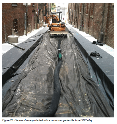
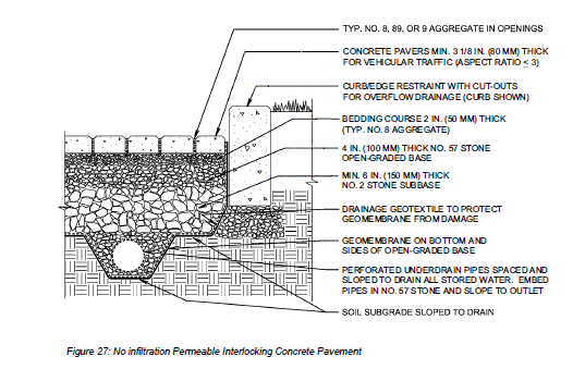
When preparing a site for a geomembrane application, rocks, roots, and other sharp objects are removed that can damage the geomembrane during installation (especially from aggregate compaction) or use. Such protrusions should be removed and voids filled with dense-graded aggregate base and compacted before placing the geomembrane over them. A layer of non-woven geotextile is commonly used to protect one or both sides of the geomembrane. The thickness of the geotextile is typically selected based on the materials placed next to the geomembrane and the degree of risk for punctures. Figure 26 illustrates a green alley in Richmond, Virginia with a geomembrane protected by a nonwoven geotextile. Both are placed before placing and compacting the open-graded aggregate subbase. Figure 27 shows the typical cross section for a No-exfiltration PICP system.
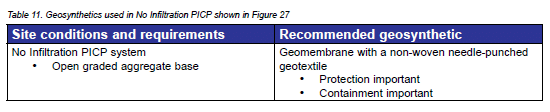
When designing a no infiltration PICP system there are many factors that must be considered in selecting the geomembrane and protection materials. In addition, geomembranes may be wrapped around utility lines to protect them from exposure to water within PICP bases/subbases. For most projects, consultation with an engineer familiar with the design of geomembranes is recommended. Table 11 provides recommendations for geomembrane and geotextile selections based on conditions and requirements.
REFERENCES
- AASHTO M-288-15 Specification for Geotextile Specification for Highway Applications, Standard Specifications for Transportation Materials and Methods of Sampling and Testing, American Association of State Highway & Transportation Officials, Washington, DC.
- ASTM D4439-15 Standard Terminology of Geosynthetics, Vol. 04.13, ASTM Book of Standards, American Society for Testing and Materials International, Conshohocken, PA.
- ASTM D4873/D4873M-16 Standard Guide for Identification Storage & Handling of Geotextiles, Vol. 04.13, ASTM Book of Standards, American Society for Testing and Materials International, Conshohocken, PA.
- Berg, R.R., Christopher, B.R. and Perkins, S. 2000. Geosynthetic Reinforcement of the Aggregate Base/ Subbase Courses of Pavement Structures, GMA White Paper II, Prepared for AASHTO Committee 4E by the Geosynthetic Materials Association, June 27, 2000.
- Holtz, R.D., Christopher, B.R. and Berg, R.R., 2008. Geosynthetic Design and Construction Guidelines Reference Manual, FHWA NHI-07–092, National Highway Institute, Federal Highway Administration, Washington, DC.
- Koerner, R. M. 2012. Designing with Geosynthetics, Xlibris Corporation.
- Kelsey, C. 2014. “A Brief History of Geotextiles” in Land and Water Magazine, Vol. 58, Issue 1, March 2014.
- Koerner, J.R. and Koerner R.M. 2006. Status of Adoption and Use of the AASHTO M288 Geotextile Specification Within U.S. State Department of Transportation, Report No. 31, Geotextile Research Institute, July 17, 2006.
- Zornberg J.G. and Thompson, N. 2010. Application Guide and Specifications for Geotextiles in Roadway Applications, Center for Transportation Research The University of Texas at Austin, Report No. FHWA/TX-10/0-5812-1.
Photos included in this publication have been provided by: Geosynthtic Institute, National Concrete Masory Association, Presto Geosystems, Tencate Mirafi