BACKGROUND
First approved in 1982, ASTM C936 Standard Specification for Solid Interlocking Concrete Paving Units (ASTM 2013) established acceptance criteria for the compressive strength of concrete pavers. Concrete pavers meeting this product standard require a minimum average of 8,000 psi (55 MPa) with no individual unit below 7,200 psi (50 MPa). Concrete paver sizes are defined in this standard as having a minimum thickness of 23/8 in. (60 mm), an aspect ratio (length divided by thickness) not exceeding 4, and a maximum surface area of 101 in.2 (0.065 m2).
ASTM C936 references the compressive strength test procedure in ASTM C140 Standard Test Methods for Sampling and Testing Concrete Masonry Units and Related Units (ASTM 2014a). This test method was revised to account for differences in compressive strength due to paver thickness starting in the ASTM C140-12a revision (ASTM 2012a). Prior to this revision, compression testing of thicker concrete pavers resulted in lower measured compressive strengths than thinner ones solely due to the increased thickness of the pavers. Relationships between specimen thickness and compressive strength for concrete have been summarized by the U.S. Department of the Interior Bureau of Reclamation (Reclamation 1975). Precedence in national standards for adjusting the compressive strength of concrete pavers based on their thickness/width ratio is in the 1993 British Standards Institute standard for concrete block paving (BSI 1993).
Decreasing compressive strength due to increasing thickness is not unique to concrete; increasing the height or thickness of any material tested for compressive strength results in lower measured strengths. To address this, ASTM C140 now adjusts the compressive strength of all concrete pavers with an aspect ratio (thickness divided by width) factor to that of a 23/8 (60 mm) by 37/8 (98 mm) thick concrete paver. This thickness was selected because the 8,000 psi (55 MPa) compressive strength requirement was originally written for this paver thickness. The rationale and calculations for adjusting concrete paver compressive strength from paver aspect ratio (thickness/width) was developed for ASTM in (NCMA 2010) and discussed in an ASTM publication (Walloch 2014). The guidance in this technical bulletin is based on these research reports.
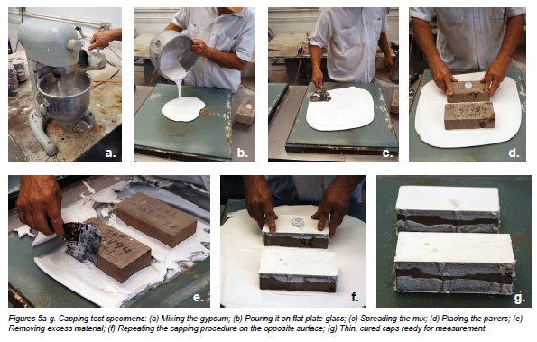
Prior to testing concrete pavers in compression, their top and bottom surfaces are thinly capped with gypsum. This material is applied as a paste and allowed to cure or harden up to 24 hours prior to compression testing. This capping provides a smooth and parallel surface on the concrete paver to uniformly engage the platen in the compression testing machine, helping to ensure even distribution of applied loads during testing. See Figure 1. ASTM C140 Annex A4, Test Procedures for Concrete Interlocking Paving Units, provides detailed instructions on capping for the concrete pavers as well as on compressive strength testing of the capped specimens. This technical bulletin covers these procedures in a step-by-step guide that testing laboratories, paver manufacturers and specifiers can use to better understand the new testing process.
COMPRESSION TESTING PROCEDURES
The process for compressive strength testing of concrete pavers consists of seven steps. By following these steps, testing laboratories can help ensure compliance with ASTM C140 Annex A4, Test Procedures for Concrete Interlocking Paving Units.
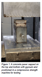
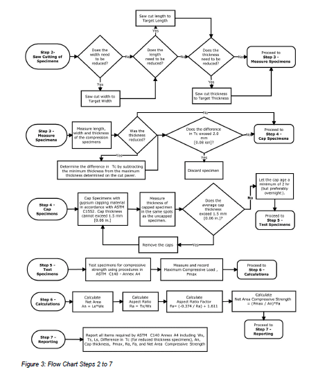
Figure 2 provides a flow chart/decision tree for determining the dimensions of the test specimen and determining if cutting is required as detailed in Step 1. Figure 3 summarizes Steps 2 through 7 described in detail below.
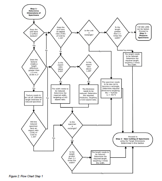
Step 1–Determine the Dimensions of the Compressive Strength Specimens
ASTM C140 Annex A4 requires that full size paver test specimens must meet the following criteria:
- A smooth top surface. If there is a surface texture, the height difference between the highest and lowest points on the surface cannot exceed 0.06 in. (1.5 mm). Grooves on pavers that imitate joints are not allowed in the test specimens. Only chamfers intentionally manufactured into the edge of the pavers are allowed.
- An aspect ratio (thickness/width) of between 0.60 and 1.20
- Rectangular shape
- Length cannot exceed 2.1 times the width.
If the full-size test specimen meets all of the criteria listed in Step 1, then it is tested full-size. It does not require cutting and the testing technician can proceed to Step 3–Measure Specimens. If the full-size test specimen does not meet all of these criteria, the specimen needs to be cut as described below. The testing technician should proceed as follows:
- Some concrete pavers are textured to simulate stone surfaces. If the paver has surface texture that exceeds 0.06 in. (1.5 mm) in difference between the highest and lowest point on the surface, then the surface must be saw cut and discarded. (This also applies to grooves on pavers that imitate joints.) Prior to cutting, the technician estimates the thickness remaining after saw-cutting the surface to obtain a smooth surface texture. The amount cut off is typically 0.4 to 0.6 in. or 10 to 15 mm thick. The estimated thickness of the final specimen should be used in the steps below.
- The approximate aspect ratio (thickness/width) of the cut testing specimen should be determined prior to cutting. If the cut test specimen with no surface texture has an aspect ratio between 0.60 and 1.20, then the technician moves to step 3 below. If not, then follow the next steps:
- If the aspect ratio is below 0.60, then the paver width must be reduced by saw cutting. Determine the required width by targeting a 0.63 aspect ratio. By targeting an aspect ratio of 0.63, the final specimen likely has an actual aspect ratio of 0.60 to 0.66 and the aspect ratio factor to adjust the compressive strength test results is between 0.988 and 1.044.
- If the aspect ratio is above 1.20, then the overall thickness of the paver must be reduced with saw cutting. The technician should determine the required thickness by targeting a 0.63 aspect ratio.
- If the paver has a rectangular shape the laboratory can then proceed to Step D. If it is not a rectangle, then a rectangular test specimen must be cut from the paver. Determine the required dimensions by targeting a width equal to the thickness/0.63 and a length equal to two times the width. If the thickness or width must be reduced, use the targeted thickness and/or width in the calculations. The technician should now have width, length and heights targets for the final specimen and can proceed to Saw Cutting Specimens.
- If the paver or test specimen is a rectangle, then the technician determines if the length is less than or equal to 2.1 times the width of the specimen. If it is less than 2.1 times the width of the specimen, the technician can proceed to Saw Cutting Specimens. If the length is greater than 2.1 times the width of the specimen, the technician should determine the required length of the specimen for saw cutting aiming for two times the length. The technician should determine the final width, length and height targets for the final test specimen and can proceed Step 2–Saw Cutting Specimens.
Step 2–Saw Cutting Specimens
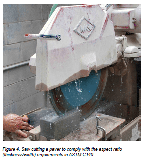
Based on the above, the test specimen needs to be saw-cut from the full-size specimen. A diamond-tipped saw blade is required on a water-cooled or dry cut table saw, both with dust controls. The technician performing the cutting should be experienced in cutting concrete pavers. Figure 4 illustrates saw cutting. The saw-cutting should be performed in the following order, which typically results in the highest quality test specimen:
- If the width of the specimen needs to be reduced, make this the first saw-cut.
- If the length of the specimen needs to be reduced, make this the next saw-cut.
- If the thickness of the specimen needs to be reduced, this should be the final saw-cut. This facilitates easier handling, since cutting the thickness can be more difficult than other cuts, and extra care is required by the technician for this operation.
Once the technician has saw-cut the specimen, proceed to Step 3–Measure Specimens with the reduced-size compression specimen.
Step 3–Measure Specimens
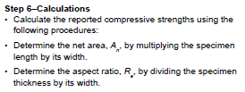
The next step is measuring the compression specimen. When tested at full size, measure full-size specimens. When specimen sizes have been reduced by cutting per Step 2, measured these specimens as well. Make all measurements using a caliper readable to 0.002 in. or 0.1 mm and record them. The following measurements are taken for compression specimens:
- Width: measured across the top and bottom surface at mid- length
- Length: measured across the top and bottom surface at mid-width.
- Thickness: measured at mid-length on each side of the paver. If the paver has a chamfer, measure the top to the bottom surfaces of the paver without measuring the chamfer.
When the thickness of the units has been cut and reduced to remove surface texture or to meet the aspect ratio (thickness/ width) requirements, an additional comparison is necessary. The measured thicknesses from each side of the paver must be compared. If the difference in thickness is greater than 0.08 in. (2.0 mm), this wedge-shaped unit must be discarded and a new specimen cut. A cut paver with a wedged shape results in lower compressive strengths due to force applied to only one side of the specimen. Once measurements are completed, the technician continues to Step 4–Cap Specimens.
Step 4–Cap Specimens
Prior to compressive strength testing, the paving units must be capped with gypsum. Similarly, compression testing of concrete cylinders are typically capped with a sulfur-based material. Research (NCMA 2008) (Walloch 2014) investigated and compared the variability of sulfur and gypsum based capping materials on compressive strength test results. The research indicated lower variability in compression testing results by using gypsum capping. Besides limiting capping materials to gypsum for concrete pavers, the research presented additional recommendations now included in ASTM C140, Annex A4.
ASTM C140, Annex A4 now requires that paver compression specimens be capped according to ASTM C1552 Standard Practice for Capping Concrete Masonry Units, Related Units and Masonry Prisms for Compression Testing (ASTM 2014) with two additional restrictions. First, the capping material must be high-strength gypsum cement. While ASTM C1552 allows for gypsum and sulfur capping material, only gypsum is acceptable for capping concrete pavers for compressive strength testing.
Second, the final cap thickness cannot exceed 0.06 in. (1.5 mm). This is half of the allowable thickness for other caps per ASTM C1552. In order to achieve thin caps, the plastic gypsum is mixed to a consistency that simultaneously achieves two objectives: (1) sufficient fluidity for spreading thinly on the capping plate while (2) having sufficient viscosity that allows the paver surface to be pushed into the plastic gypsum, thereby forming a consistent thin cap. The technician must also be careful not to exceed the water to cement ratio determined to provide needed capping material compressive strength. Figure 5 illustrates settng test specimens into the plastic capping material which has the consistency of thick pancake batter.
In order to determine an acceptable cap thickness after capping, the specimen is measured again for thickness after the capping has hardened. Measurements are taken in the same locations as before capping. At each point, the before capped thickness is subtracted from the capped thickness. This value is divided in half (there are two caps) and then the resulting cap thickness is determined by averaging the measurement in each location.
The average cap thickness cannot exceed 0.06 in. or 1.5 mm. If the cap thickness is greater, the technician must remove the caps and repeat the capping operation.
If the caps have an acceptable thickness upon hardening, i.e., less than or equal to the maximum average thickness, the caps must age before performing compressive strength testing. The minimum time required between capping specimens and testing them is two hours, but overnight aging is preferred. The curing time begins when the second cap is placed on each paver specimen. Following curing of caps, the technician can proceed to Step 5–Test Specimens.
Step 5–Test the Specimens
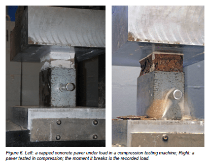
Perform compression testing according to ASTM C140. Center the paver specimen in the testing machine and estimate the expected load. Load each specimen to half the expected breaking load at a convenient rate. The second half of the expected breaking load is applied in no less than one minute and no longer than two minutes. Figure 4 shows the capped paver loaded and then breaking. Record the total load (Pmax ). Proceed to Step 6–Calculations.
Step 7–Reporting
The following information is reported by the testing laboratory for compressive strength as required by ASTM C140 Annex A4:
- The average width, W, thickness, T, and length, L, to the nearest 0.002 in or 0.1 mm. These dimensions are reported separately for each full-sized, sampled unit and as the average for the three units tested.
- The dimensions of the compression specimens (Ws , Ts , and Ls ), to the nearest 0.002 in. or 0.1 mm, if different from the full-size units. This includes the difference among the four thickness measurements taken across the face of the paver if the specimen was cut to reduce its thickness.
- The net area to the nearest 0.01 in.2 or 10 mm2 separately for each compression specimen and as the average for the three specimens tested
- The average cap thickness to the nearest 0.002 in. or 0.1 mm for each compression specimen and as the average for the set of three specimens tested
- The maximum load, separately for each specimen and as the average for the three specimens tested. Report the load as indicated to the nearest 10 lb or 50 N or the minimum resolution of the test machine as used during testing, whichever is greater.
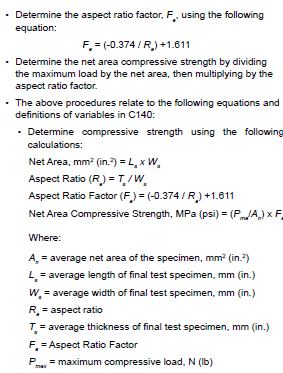
- The aspect ratio, Ra , and aspect ratio factor, Fa , for each compressive strength test specimen.
- The net area compressive strength to the nearest 10 psi or 0.1 MPa separately for each specimen and as the average for three specimens tested.
CONCLUSIONS
Since its initial approval in 1982, ASTM C936 is being applied to a wider range of paver shapes and thicknesses. Initially, ASTM C936 did not anticipate or account for the differences in compressive strength due to various shapes, thicknesses and resulting thickness-to-width ratios. Additionally, concrete paver manufacturers indicated high variability in test results especially between different testing laboratories. This technical bulletin addresses these differences based on comprehensive testing research, review of the research and balloting of revisions to ASTM C140 and C936 by ASTM C15.03 Subcommittee on Concrete Masonry Units and Related Units and ASTM C15 Committee on Manufactured Concrete Masonry Units. This bulletin presents a step-by-step guide for use by testing laboratories to better understand ASTM requirements. In addition, the information supports more consistent test results from concrete paver manufacturers and for project specifiers and contractors.
REFERENCES
- ASTM 2012. ASTM C1553-12, Standard Practice for Capping Concrete Masonry Units, Related Units and Masonry Prisms for Compression Testing, Vol. 04.05, Annual Book of Standards, ASTM International, West Conshohocken, PA, www.astm.org.
- ASTM 2013. ASTM C936/C936M-13, Standard Specification for Solid Concrete Interlocking Paving Units, Vol. 04.05, Annual Book of Standards, ASTM International, West Conshohocken, PA, www.astm.org.
- ASTM 2013a. ASTM C140/C140M-13a: Standard Test Methods for Sampling and Testing Concrete Masonry Units and Related Units, Annual Book of Standards, Vol. 04.05, ASTM International, West Conshohocken, PA, www.astm.org.
- BSI 1993. British Standard BS 6717: Part 1, Precast Concrete Paving Blocks, British Standards Institute, London, United Kingdom, www.bsigroup.com.
- NCMA 2008. NCMA Project No. 07-592, “Assessment of the Influence of Capping Variables on the Measured Compressive Strength of Concrete Paving Units,” National Concrete Masonry Association, Herndon, VA, www.ncma. org.
- NCMA 2010. Project No. 09-105, “Evaluation of the Test Specimen Size on the Measured Compressive Strength of Solid Concrete Paving Units”, National Concrete Masonry Association, Herndon, VA, www.ncma.org.
- Reclamation 1975. Concrete Manual: A Method for the Control of Concrete Construction, U.S. Department of the Interior – Bureau of Reclamation, 8th Edition, p. 575, A Water Resources Publication, revised 1981, reprinted 1988, Washington, DC.
- Walloch 2014. Walloch, C, Lang, N, and Smith, D.R., “Compressive Strength Testing of Concrete Paving Units: Research on Configuration of Tested Specimens and Effects of Variables in Specimen Capping,” ASTM Selected Technical Papers (STP) accepted for STP publication by ASTM, Manuscript ID STP-2013-0181.R1, February 2014, ASTM International, Conshohocken, PA.
