
Revised 2022
INTRODUCTION
Permeable interlocking concrete pavement (PICP) is recognized by federal and state stormwater and transportation agencies as a Best Management Practice (BMP) and Low Impact Devel- opment (LID) tool to reduce runoff and water pollution. In addition, PICP offers unique design opportunities for addressing combined sewer overflows with green alleys and streets, as well as use in parking lot and pedestrian surfaces. Traditional stormwater management solutions focus on collecting, concentrating and centralizing the disposal of stormwater. As a key BMP and LID tool, PICP helps disconnect, decentralize and more widely distribute runoff through infiltration, detention, filtering and treatment.
The Concrete Masonry and Hardscapes Association (CMHA) provides a comprehensive manual entitled Permeable Interlocking Concrete Pavements, which covers design, specifications, construction and maintenance. This manual is available on www.masonryandhardscapes.org and provides extensive information from academic research and practical field experience. This Tech Note bulletin provides a summary of PICP construction techniques outlined in the manual, as well as further guidance on best construction practices. This bulletin is intended for contractors and for project inspectors.
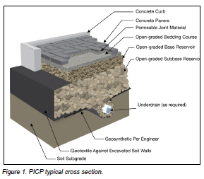
Figure 1 illustrates a typical PICP cross-section with the individual components defined below.
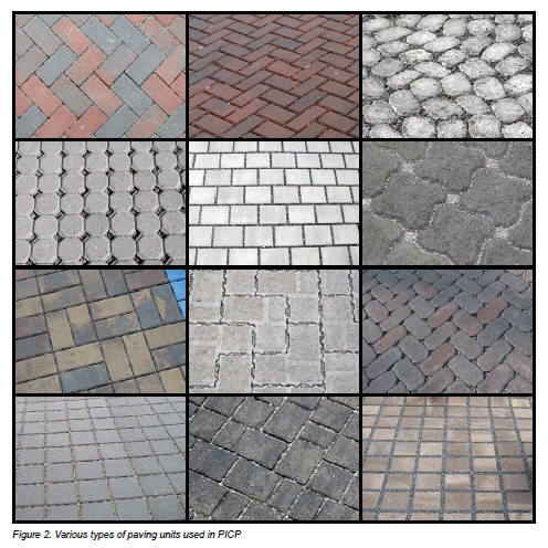
Concrete pavers—Solid concrete pavers with molded joints and/or openings that create an open area across the pavement surface. Concrete pavers should conform to ASTM C936 in the U.S. or CSA A231.2 in Canada. Pavers are typically a minimum of 3 1/8 in. (80 mm) thick for vehicular areas and pedestrian areas may use 2 3/8 in. (60 mm) thick units. Pavers are manufactured in a range of shapes and colors. Filled with permeable joint material, the openings allow water from storm events to freely infiltrate through the pavement surface. Figure 2 shows several paver configurations.
Permeable Joint Material—The joint material typically consists of angular ASTM No. 8, 89 or 9 stone. The permeable joints allow stormwater to infiltrate through joints in the pavement surface.
Open-graded bedding course—This permeable layer is typically placed as a 2 in. (50 mm) thick lift and provides a setting bed for the pavers. It consists of small-sized, open-graded angular aggregate, typically ASTM No. 8 stone or similar sized material. After paver compaction this lift will consolidate slightly.
Open-graded base reservoir—This is an aggregate layer that is typically 4 in. (100 mm) thick (for vehicular applications see exception under subbase definition). The base material is made of crushed stones primarily 1 in. down to 1/2 in. (25 mm down to 13 mm). For pedestrian application the base layer is a minimum of 6 in. (150 mm) and the subbase may be omitted. Besides providing water storage capacity in the spaces among the stones, this highly permeable material also serves as a choking layer between the bedding and subbase layers. The stone size is typically ASTM No. 57 or similar sized material.
Open-graded subbase reservoir—The stone sizes are larger than the base, primarily 3 in. down to 2 in. (75 mm down to 50 mm), typically ASTM No. 2, 3 or 4 stone. Like the base layer, water is stored in the spaces among the stones. The subbase layer thickness depends on water storage requirements and traffic loads. A subbase layer may not be required in pedestrian or residential driveway applications. In such instances, the base layer thickness is increased to provide water storage and support.
Underdrain (as required)—Where PICP is installed over low- infiltration soils, underdrains facilitate water removal from the base and subbase. The underdrains are perforated pipes that drain to a swale or stream, or connect to an outlet structure. Another option to which underdrains connect is plastic or concrete vaults or plastic crates. These can store significant amounts of runoff.
Geotextile (design option per engineer)—This functions primarily as a separation and filtration material between the subbase and subgrade by preventing the migration of soil into the aggregate subbase or base. Geotextiles are required along the sides of most PICP applications.
Subgrade Soil—This is the layer of soil immediately beneath the aggregate base or subbase. The infiltration rate of the saturated subgrade determines how much water can drain from the aggregate into the underlying soils. The subgrade soil is generally not compacted as this can substantially reduce soil infiltration. However, some poorly draining clay soils are often compacted to help ensure structural stability especially when saturated. Since compaction reduces infiltration, managing the excess water must be considered in the hydrologic design via the base/subbase thickness and use of perforated pipe underdrains.
BENEFITS
PICP offers a number of benefits compared to other common pavement systems.
CONSTRUCTION
- Immediately ready for traffic upon completion, no additional time needed for curing
- Can be installed in cold weather if subgrade and aggregates remain unfrozen
- Capable of wet weather (light rain) installation
- No time-sensitive materials that require site forming and management for curing
- Contractor training and credentials available through CMHA
REDUCED RUNOFF
- Up to 100% surface runoff reduction (subject to design requirements)
- Up to 100% infiltration depending on the design and soil subgrade infiltration rate
- Capable of installation over or next to plastic underground storage vaults or crates
- Can be designed with water harvesting systems for site irrigation and gray water uses
- Contributes to reduction in downstream flooding
IMPROVED WATER QUALITY
- Reduces total suspended solids by up to 100% depending on the design of the system.
- Reduces nutrients, metals and oils
- By storing water below grade, runoff temperatures are not elevated which can damage aquatic life
- Can be used to achieve water quality capture volume
- Can be used to achieve total maximum daily load (TMDL) limits for a range of pollutants
SITE UTILIZATION
- Reduces or eliminates unsightly detention/retention ponds
- Increased site and building utilization
- Conservation of space on the site and reduction of impervious cover
- Preserves woods and open space that would have been destroyed for detention ponds
- Promotes tree survival by providing air and water to roots (roots do not heave pavement)
DRAINAGE SYSTEM
- Reduced downstream flows and stream bank erosion due to decreased peak flows and volumes
- Increased recharge of groundwater
- Decreases risk of salt water incursion and drinking water well pollution in coastal areas
- Reduced peak discharges and stress on storm sewers
- Reduces combined sanitary/storm sewer overflows
REDUCED OPERATING COSTS
- Can result in a reduction in overall project costs due to the reduction or elimination of storm sewers and drainage appurtenances
- Lower life-cycle costs than conventional pavements
- Capable of integration with horizontal ground source heat pumps to reduce building heating and cooling energy costs
- Enables landowner credits on stormwater utility fees
- Does not require sealing which lowers maintenance costs
PAVER SURFACE UNITS
- 50-year design life based on proven field performance
- Most styles are ADA compliant
- Colored units can mark parking stalls and driving lanes; light colors can reduce night time lighting needs
- Eliminates puddles on parking lots, walkways, entrances, etc.
- Capable of plowing with municipal snow removal equipment
- Durable, high-strength, low-absorption concrete units resist freeze-thaw, heaving and degradation from deicing materials
- Reduced ice and deicing material use/costs due to rapid ice melt and surface infiltration
- Reduced liability from slipping on ice due to rapid ice melt and surface infiltration
- Provides traffic calming
- Paver surface can be coated with photocatalytic materials to reduce air pollution
- Units with high Solar Reflectance surfaces help reduce micro-climatic temperatures and contributes to urban heat island reduction
- Units manufactured with recycled materials and cement substitutes reduce greenhouse gas emissions
SIMPLER MAINTENANCE & REPAIRS
- Paving units and base materials can be removed and reinstated
- Utility cuts into the pavement do not cause damage to the surface that can in turn decrease pavement life
- Capable of winter repairs
- No unsightly patches from utility cuts
- Surface cleaning with standard vacuum equipment
- Clogged surfaces may be restored with vacuum equipment to reestablish high infiltration rates
SYSTEM BASICS
PICP is recommended in the following areas:
- Residential patios, walks and driveways.
- Walks, parking lots, main and service driveways around commercial, institutional, recreational and cultural buildings.
- Low speed (<35 mph or 56 kph) residential roads.
- Non-commercial boat landings and marinas.
- Storage areas for shipping containers with non-hazardous contents.
When evaluating a site, the following characteristics should be considered:
- Runoff from contributing at-grade impervious areas does not
- exceed five times the area of the PICP receiving the runoff.
- The estimated depth from the bottom of the pavement base, for full or partial infiltration systems, to the seasonal high level of the water table is greater than 2 feet (0.6 m). Greater depths may be required to obtain additional filtering of pollutants through the soil.
- PICP is down slope from building foundations and the foundations have piped drainage at the footers. Waterproofing such as an impermeable liner is recommended on basement walls against PICP.
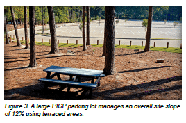
- The slope of the permeable pavement surface should be less than 12% and is typically 5% or less. Figure 3 illustrates parking lot near Atlanta, Georgia that uses terraced levels to address the slope of 12% across the site.
- At least 100 ft (30 m) should be maintained between PICP and water supply wells. (Local jurisdictions may provide additional guidance or regulations.)
- Sites where the owner can meet maintenance requirements.
- Sites where runoff draining onto PICP surface is not from soil erosion, exposed topsoil or mulch.
- Sites where there will not be an increase in impervious cover draining into the PICP (unless the pavement is designed to infiltrate and store runoff from future increases in impervious cover due to future development).
- Sites where space constraints, high land prices, tree/green space conservation, land used by detention facilities, and/ or runoff from additional development make PICP a cost- effective solution.
- Sites outside permafrost regions
SITES TO AVOID
PICP is not recommended on any site classified as a storm water hotspot, i.e., if there is any risk that storm water can infiltrate and contaminate groundwater. These land uses and activities may include the following:
- Vehicle salvage yards, recycling facilities, fueling stations, service and maintenance facilities, equipment and cleaning facilities
- Fleet storage areas (bus, truck, etc.)
- Commercial marina service and maintenance areas
- Outdoor liquid container storage areas
- Outdoor unloading facilities in industrial areas
- Public works materials/equipment storage areas
- Industrial facilities that generate or store hazardous materials
- Storage areas for commercial shipping containers with contents that could damage groundwater and soil
- Other land uses and activities not suitable for infiltration as designated by an appropriate review authority
BASIC PICP SYSTEMS
PICP can be built with full, partial or no infiltration of the open- graded stone base into the soil subgrade.
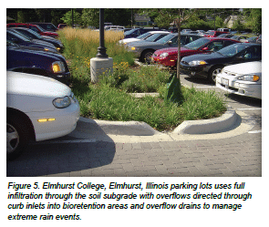
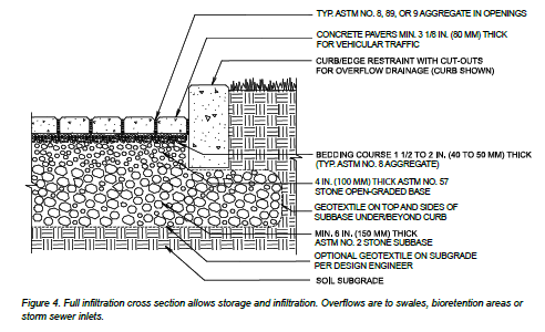
Full Infiltration—Full infiltration directs water through the base/ subbase and infiltrates into the soil subgrade. This is the most common application over high infiltration soils such as gravels and sands. Overflows can exit through the surface if necessary, but one of the strategies mentioned above is better if feasible. Figure 4 illustrates schematic cross-section of a full infiltration PICP. Overflow drainage can exit from the surface but is better managed via large drainpipes from within the base. Figure 5 illustrates an example of handling PICP overflows via curb inlets to bioswales.
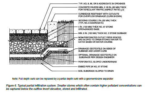
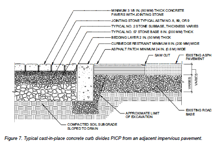
Partial Infiltration—Partial infiltration relies on drainage of the base/subbase into the subgrade soil and drainage pipes to direct excess water to a stormsewer, daylight or a stream. This controls the amount of time the subgrade is saturated. This design is common to lower infiltration rate soils such as silts and clays. Perforated drain pipes are typically placed in trenches in the subbase and covered with ASTM No. 57 stone to protect them while the ASTM No. 2 stone is compacted. Figure 6 illustrates a schematic cross-section of partial infiltration design. Figure 7 shows a full depth concrete grade beam being used to separate the open graded base from the adjacent pavement structure.
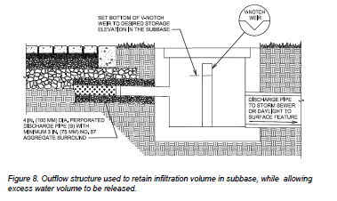
Outflow from the system is controlled by the outflow structure which retains a specific amount of water which is calculated to infiltrate into the subgrade in the specified amount of time. Water is typically detained for 24 to 48 hours. Soils with infiltration rates as low as 0.01 in./hr (7 x 10⁻⁶ cm/sec) can infiltrate about 0.5 in. (13 mm) over 48 hours. Stormwater in excess of the infiltration volume will flow over the weir and out of the system. The weir is designed to control the discharge volume and rate. Figure 8 shows the outflow control structure.
No Infiltration—This is required when the soil has very low permeability or low strength, or there are other site limitations. The assembly is a detention pond with an outlet. An impermeable geomembrane may be used if the pollutant loads are expected to exceed the capacity of the base/subbase and soil subgrade to treat them. The geomembrane can be high density polyethylene (HDPE), ethylene propylene diene monomer (EPDM) or polyvinyl chloride (PVC) or other similar material. Geomembranes typically require a non-woven geotextile for additional protection during aggregate filling and compaction. No infiltration is also used for creating a reservoir for water harvesting or horizontal ground source heat pumps that augment nearby building heating and cooling needs.
No infiltration designs with geomembranes are:
- Over aquifers with insufficient soil depth to filter the pollutants before entering the ground water. These can include karst, fissured or cleft aquifers.
- Over fill soils whose behavior when exposed to infiltrating water may cause unacceptable settling and movement. These might include expansive soils such as loess, poorly compacted soils, gypsiferous soils, etc.
DESIGN CONSIDERATIONS
A preliminary assessment is an essential prerequisite to detailed site, hydrological and structural design. This assessment includes a review of the following:
- Underlying geology and soils maps
- Identifying the NRCS hydrologic soil groups (A, B, C, D)
- Verifying history of fill soil, previous disturbances or compaction
- Review of topographical maps and identifying drainage patterns
- Identifying streams, wetlands, wells and structures
- Confirming absence of stormwater hotspots
- Identifying current and future land uses draining onto the site
PICP design involves structural and hydrological analyses. PICP design merges these two previously disconnected spheres of civil engineering and design. The base/subbase thickness is determined for hydrological and structural (vehicular traffic loading) needs, and the thicker section is selected for drawings, specifications and construction. In many cases, the hydrologic requirements will require a thicker base than that required for supporting traffic. The design process for PICP is outlined in the Figure 9 flow chart. Detailed design guidance is available in CMHA manual Permeable Interlocking Concrete Pavement, 5th Edition and the American Society of Civil Engineers Permeable Interlocking Concrete Pavement Standard 68-18.
CONSTRUCTION OVERVIEW
PICP construction for parking lots and roads involves the steps listed below and explains some variations depending on the application. In addition, a guide specification is available at www.masonryandhardscapes.org and can be downloaded and edited to project conditions.
Pre-construction meeting—For commercial and municipal projects, the specifications should include a pre-construction meeting. The pre-construction meeting is held to discuss methods of accomplishing all phases of the construction operation, contingency planning, and standards of workmanship. The general contractor typically provides the meeting facility, meeting date and time. Representatives from the following entities should be present;
- General Contractor superintendent.
- PICP subcontractor foreman.
- Concrete paving unit manufacturer’s representative.
- Testing laboratory(ies) representative(s).
- Engineer or owner’s representative.
- Other affected trades or representatives who will access PICP area.
The following items should be discussed and determined:
- Test panel (mock-up) location and dimensions.
- Methods for keeping all materials free from sediment during storage, placement, and on completed areas.
- Methods for checking slopes, surface tolerances, and elevations.
- Concrete paving unit delivery method(s), timing, storage location(s) on the site, staging, paving start point(s) and direction(s).
- Anticipated daily paving production and actual record.
- Diagrams of paving laying/layer pattern and joining layers as indicated on the drawings
- Monitoring/verifying paver dimensional tolerances in the manufacturing facility and on-site if the concrete paving units are mechanically installed.
- Testing intervals for sieve analyses of aggregates and for the concrete paving units.
- Method(s) for tagging and numbering concrete unit paving packages delivered to the site.
- Testing lab location, test methods, report delivery, contents and timing.
- Engineer inspection intervals and procedures for correcting work that does not conform to the project specifications.
- Procedure for testing and approval of subgrade, sub- base and base including compaction.
- Curb type and installation schedule.

Plan site access and keeping PICP materials free from sediment—Preventing and diverting sediment from entering the aggregates and pavement surface during construction must be the highest priority. Extra care must be applied to keeping sediment completely away from aggregates stored on site as well as the PICP. In some cases, it may be necessary to construct PICP before other soil-disturbing construction is completed. The options below are for ensuring that the PICP does not become contaminated with sediment from construction vehicles. The options below are in ascending cost order. One or more of these options should be decided in the project planning stages and included in the specifications and drawings.
- Install the PICP first and allow construction traffic to use the finished PICP surface. When construction traffic has ceased and adjacent soils are stabilized with vegetation or erosion control mats, clean the PICP surface and joints with a vacuum machine capable of removing an inch (25 mm) of the stone from the joints. Vacuum a test area and inspect the joints when stone is removed to be sure there are no visible traces of sediment on the stone remaining in the joints. If it is visible, then vacuum out jointing stones until no sediment is present. Fill the joints with clean stones and sweep the PICP surface clean.
- Protect finished PICP system by covering the surface with a heavy woven geotextile, plywood or other barrier material and a minimum 2 in. thick No. 8 open-graded aggregate layer. This aggregate layer and protective layer are removed upon project completion and when adjacent soils are stabilized with vegetation or erosion control mats. The PICP surface is swept clean.
- Construct the aggregate subbase and base and protect the surface of the base aggregate with geotextile and an additional 2 in. (50 mm) thick layer of the same base aggregate over the geotextile. Thicken this layer at transitions to match elevations of adjacent pavement surfaces subject to vehicular traffic. A similar more costly approach can be taken using a temporary asphalt wearing course rather than the additional base aggregate and geotextile. When construction traffic has ceased and adjacent soils are vegetated or stabilized with erosion control mats, remove geotextile and soiled aggregate (or the asphalt) and install the remainder of the PICP system per the project specifications.
- Establish temporary road or roads for site access that do not allow construction vehicle traffic to ride over and contaminate the PICP base materials and/or surface with mud and sediment. Other trades on the jobsite need to be informed on using temporary road(s) and staying off the PICP. The temporary road is removed upon completion of construction and opening of the PICP surface to traffic.
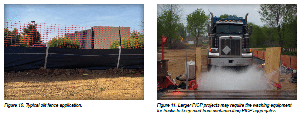
Other practices such as keeping muddy construction equipment away from the PICP, installing silt fences, staged excavation, and temporary drainage swales that divert runoff away from the area will make the difference between a pavement that infiltrates well or poorly. Figure 10 illustrates a silt fence.
Another more involved practice is a washing station for truck tires. Larger PICP projects may require this level of cleanliness as trucks enter a muddy PICP site. Figure 11 illustrates truck washing equipment which naturally requires disposal of dewatered sediment.
Excavate soil or an existing pavement—In some cases, the excavated area for base and PICP can be used as a sediment trap if there is time between the excavation and aggregate base installation. This is done by excavating within 6 in. (150 mm) of the final bottom elevation. This area can contain water during storms over the construction period and exit via temporary drain pipes. Heavy equipment should be kept from this area to prevent compaction. If equipment needs to traverse the bottom of the excavation, tracked vehicles can reduce the risk of soil compaction. As the project progresses, sediment and the remaining soil depth can be excavated to the final grade immediately before installing the aggregate subbase and base. Depending on the project design, this technique might eliminate the need for a separate sediment basin during construction.
Avoid soil compaction unless required in the plans and specifications—As discussed previously, soil compaction as part of the design is the engineer’s decision and should be executed according to the project specifications. If compaction is not specified, the initial undisturbed soil infiltration should be carefully maintained during excavation and construction as this will enable the base to drain as designed. If the soil is inadvertently compacted by equipment during construction, there will be substantial loss of infiltration. A loss may be acceptable if the infiltration rate of the soil when compacted was initially considered during design and in drainage calculations.
If another contractor is responsible for the excavation, subgrade preparation and compaction, they should provide the paver contractor written assurance that the subgrade has been prepared to the specification.
Install geotextiles, impermeable liners and drain pipes if required in the plans and specifications—Geotextiles are used in some permeable pavement applications per the design engineer. If there are no concrete curbs and soil is restraining the sides of the base/subbase at its perimeter, then geotextile should be applied to prevent lateral migration of soil into the base/subbase aggregates. Geotextile is applied vertically against the soil with at least 1 ft (0.3 m) extending horizontally under the subbase and resting on the soil subgrade. A minimum 1 ft (0.3 m) overlap is recommended in stronger subgrade soils and 2 ft (0.6 m) overlap on poor-draining weaker soils (CBR<5%).
When specified, impermeable liners require assembly per the manufacturer’s instructions at the shop or job site. Once assembled, they should be tested for leaks with special attention to seams and pipe penetrations.
Drain pipes are installed according to plans and specifications and should be rigid PVC or rigid double wall HDPE. Designs should have curb cut-outs or drain pipes from the PICP entering swales or storm sewer catch basins to handle overflow conditions. A minimum of 12 in. (300 mm) aggregate cover is recommended over drainpipes to protect them from damage during subbase or base compaction.
If there is a risk of drain pipe damage, consider using a heavy gauge pipe or test the pipe and base in a trial area with compaction equipment prior to placing and compacting a large area. Perforations in pipes should terminate 1 ft (0.3 m) short of the sides of the opening for the base. When corrugated metal drain pipes are used, they should be aluminized, and aluminized pipe in contact with concrete should be coated to prevent corrosion. Perforated drain pipes should have caps fastened to the upslope ends. Daylighted drain pipes require wire mesh over the openings to keep out debris and animals.
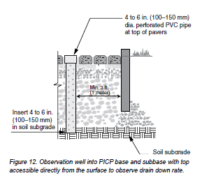
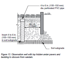
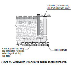
Observation Wells—A 4 to 6 in. (100 to 150 mm) diameter vertical perforated pipe that serves as an observation well may be specified in PICP subject to vehicular traffic. The pipe should be kept vertical during filling of the excavated area with open- graded aggregate and during compaction. The bottom of the pipe can be forced into the soil subgrade and held in place during base/subbase filling and compaction. The pipe should be located in the lowest elevation and a minimum of 3 ft (1 m) from the PICP side. Figures 12, 13 and 14 illustrate a well accessible from the surface and another with the pipe under the pavers to prevent damage from vandals.
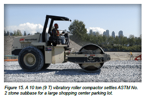
Place and compact the aggregate subbase—ASTM No. 2 subbase material should be spread in lifts up to 6 in. (150 mm). Wet or mist aggregrate base and subbase to enhance compaction effectiveness and reduce dust exposure. Compaction is typically done with a 10 ton (9 T) steel vibratory roller, where space allows. In smaller applications or where a roller is impractical, a large reversible plate compactor can be used. When using a roller, the first two passes are in vibratory mode and the last two are in static mode. Compaction is completed when no visible movement can be seen in the base when rolled by the compactor. Figure 15 illustrates a vibratory roller compacted No. 2 stone subbase.
Industry best practice is to use a 13,500 lbf reversible plate compactor to compact the open graded aggregate subbase and base. If a smaller 10,000 lbf reversible plate compactor is used, thinner lifts may be required to achieve optimum compaction. This means more passes, more time and greater expense. Plate compactors are needed to compact in corners and edges where roller compactors are not effective. Aggregates should not be crushed by the compactor. Surface tolerance of the compacted ASTM No. 2 shall be +/- 21/2 in. (65 mm) over a 10 ft. (3 m) straightedge. If another contractor is responsible for the placement and compaction of the base/subbase, they should provide the paver contractor written assurance that the base/ subbase has been prepared to the specification.
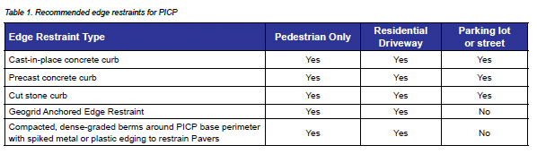
Install curbs or other edge restraints—The selection of edge restraints depends on whether the PICP is for pedestrian, residential driveway or vehicular use. Table 1 summarizes recommended edge restraint type based on the application.
Cast-in-place concrete, precast concrete and cut stone curbs are typically a minimum of 9 in. (225 mm) high and rest on the compacted No. 2 stone subbase. Consideration should be given to installing a concrete haunch under precast concrete or stone curbs. Curbs may be higher than 9 in, (225 mm) if they hold back grass, a sidewalk, bioswale or other structure. Figure 6 illustrates typical curb cross-section.
If PICP is adjacent to existing impervious asphalt or concrete pavement, curbs level with the permeable and impervious surfaces are used. The curb should extend the full depth of the base under the impermeable pavement to protect its base from becoming weakened from excessive water. Separate the two bases with an impermeable liner to protect its base from becoming weakened from excessive water. Another option is to install a full depth curb. Figure 7 shows a concrete curb between impervious pavement and PICP base and subbase.
The risk of water weakening the base under the impervious pavement can be substantially decreased by sloping the soil subgrade under the PICP away from the impervious pavement base and by using perforated drain pipes to remove water before it can collect next to the base supporting the impervious pavement. Curbs installed against existing impervious pavement and base may cause erosion and weakening of the base from excavation due to installing the PICP. Eroded spaces can be filled with concrete to support the asphalt or concrete surface and base next to the curb.
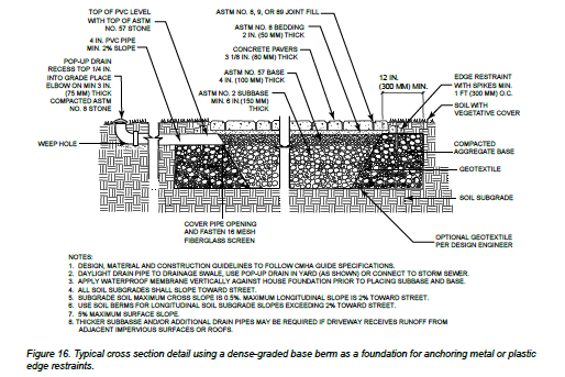
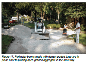
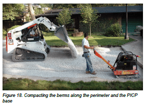
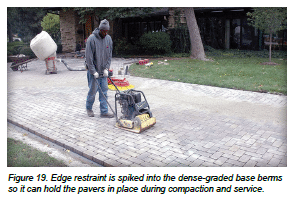
For pedestrian areas and residential driveways, an edge restraint option is using compacted, dense graded berms around PICP base perimeter with plastic or metal edging fastened to their surface. The dense-graded base is a foundation for metal or plastic edging secured with steel spikes. These edge restraints are installed on the dense-graded berms in a manner identical to those on interlocking concrete pavement driveways. Figure 1 shows a typical cross-section of this construction and Figure 2 illustrates the berms in place prior to filling the driveway with open-graded aggregate. Figure 18 shows compaction of both types of bases. Figure 19 shows the pavers in place against a plastic edge restraint spiked or nailed into the dense-graded base. The edge restraint contains some of the bedding layer such that at least the bottom half of the pavers is also contained by the edging.
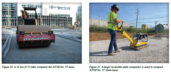
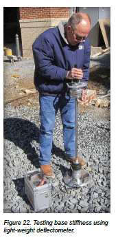
Place and compact the aggregate base—The ASTM No. 57 base layer is spread and compacted as one 4 in. (100 mm) lift. Like the subbase aggregate, the initial passes with the roller can be with vibration to consolidate the No. 57 base material as shown in Figure 20. Alternativley, a larger reversilble plate compactor the same as for subbase aggregate compaction, can be used as shown in Figure 21. Surface tolerance of the compacted No. 57 stone shall be +/- 3/4 in. (19 mm) over a 10 ft. (3 m) straightedge.
Equipment drivers should avoid rapid acceleration, hard braking, or sharp turning when driving on the compacted No. 2 subbase and on the No. 57 base. Tracked equipment is recommended. If the subbase or base surfaces are disturbed, they should be re-leveled and re-compacted.
A test section of the subbase and base should be constructed initially for compaction monitoring. The section will indicate settlement of the pavement section, and be used to monitor and prevent crushing of the aggregate. The area should be used to train inexperienced construction personnel on compaction techniques.
To confirm the compaction of an open graded aggregate CMHA recommends evaluating its stiffness using a lightweight deflectometer (LWD) shown in Figure 22 and the test method described in ASTM E2835 Standard Test Method for Measuring Deflections using a Portable Impulse Plate Load Test Device. For a compacted open-graded base layer over a compacted subbase, the user tries to achieve a maximum average deflection not greater than 0.5 mm.
The test method requires three weight drops to seat the plate. Then the machine records the deflection from the next three drops and calculates the average deflection. As the force is instantaneously applied, the plate presses into the soil or aggregate. The amount of plate movement or deflection is directly related to the stiffness of the compacted soils or base. This easy- to-use test method does not require soil testing in the lab nor operator certification. The machine also calculates a resilient modulus. Each test (all six drops) takes about 2 minutes, so a number of tests across a site can be conducted quickly.
LWD testing is a relatively new technology from Germany gaining broad acceptance by state and provincial DOTs for testing the stiffness of compacted soils, as well as dense- graded and open-graded aggregates.
If a light-weight deflectometer is not available, a nuclear density gauge running in backscatter mode can be used to test the density of the No. 57 base layer (Figure 23). The guide construction specification includes guidance on this test method. The purpose of this test method is to attain consistent density and is not as consistent as the LWD test method. Besides nuclear density gauges, (nonnuclear) stiffness gauges may also be used to assess compacted base density.
Place and screed the bedding layer—When subbase and base lifts are compacted the surface should then be topped with a 2 in. (50 mm) thick layer of No. 8 crushed stone bedding layer. This layer is screeded and leveled over the No. 57 base. Metal rails are placed on the compacted No. 57 layer and are used to guide screeding elevations. Various sizes of screeding equipment can be used ranging from hand tools, bucket screeds powered manually or by machine, or a modified asphalt spreader that uses a laser guidance system to maintain elevations. Figure 24 and 25 illustrate examples of screeding equipment. A moist bedding layer facilitates screeding.
The surface tolerance of the screeded No. 8 bedding material should be ± 3/8 in. over 10 ft. (± 10 mm over 3 m). The concrete pavers should be placed immediately after the No. 8 stone bedding is placed and screeded. Construction equipment and foot traffic should be kept off the screeded layer.
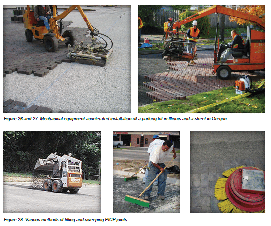
Install the pavers manually or with mechanical installation equipment—After screeding the bedding material, the pavers are placed on this layer. Paver installation can be by hand or with mechanical equipment. Spacing between units is 1/2 in. (12 mm) or less in order to comply with ADA requirements. Mechanized installation may be a cost-efficient means to install the units and reduces installation time. Figure 26 and 27 shows mechanized equipment placing permeable paver layers manufactured for placement in their final laying pattern. Mechanical installation requires careful planning including selection available paver layer patterns from local manufacturers and well-orchestrated material flow logistics in order to gain efficiencies. For further information on mechanical installation, consult CMHA Tech Note PAV-TEC-011—Mechanical Installation of Interlocking Concrete Pavements and CMHA Tech Note PAV-TEC-015—A Guide for the Specification of Mechanically Installed Interlocking Concrete Pavements.
An important consideration on large mechanical installation projects is monitoring paver production mold wear. Tech Note PAV-TEC-015 covers managing dimensional growth of pavers and provides means for confirming dimensions of the pavers at the factory and on the job site. Managing paver dimensions should be decided between the paver manufacturer and paver installation contractor and confirmed at the pre-construction meeting.

Border courses consisting of mostly whole (uncut) pavers are typically used against curbs at PICP edges and at transitions to other pavement surfaces. Paving units abutting border courses should be cut to fill spaces prior to compaction. Cuts should provide gaps around the entire perimeter of the stone that are consistent with the typical joint size—this will allow for proper interlock between units and prevent direct paver on paver contact. Cut units should be no smaller than one-third of a whole unit if subject to vehicular traffic. All installed units should have joints filled and compacted within 6 ft (2 m) of the laying face at the end of each day.
Filling the paver joints and sweep the surface clean—The paver joints are filled with ASTM No. 8, 89 or 9 stone. Depending on the PICP area, spreading and sweeping can be done with shovels and brooms, or larger areas with machines and swept into the paver joints with powered brooms or sweepers. Once the joints are full (within 1/4 in. or 6 mm of the paver surface), the surface must be swept clean prior to compaction as loose stones on the surface can mar the pavers when in contact with a plate compactor. Figure 28 illustrates various filling and sweeping methods.Compact the pavers—After the PICP surface is swept clean, it is compacted with a plate compactor. A minimum of two passes should be made with the second pass in a perpendicular direction from the first pass. The path of the plate compactor should overlap several inches (cm). The plate compactor should exert a minimum 5,000 lbf (22 kN) at 75 to 90 Hz. Figure 29 shows permeable pavers being compacted for a street project using a large plate compactor.

Top up joints with joint filling stone as needed and sweep the surface clean—Compaction can cause some settlement of the aggregates inside the joints. If the aggregates are more than 1/4 in. (6 mm) from the paver surface, they should be topped up to this level with additional aggregates. The paver surface should be swept clean prior to opening the PICP to traffic.
Aggregates in the paver joints can settle in early in the life of the pavement. Some settlement can be reduced through consistent, thorough compaction of the base, pavers and bedding layers. However, it is advisable for the contractor to return to the site after six months, inspect the joints and top them up with aggregate if they have settled to more than 1/4 in. (6 mm) below the paver surface. This service should be included in the construction specifications.
CONSTRUCTION CHECKLIST
The following provides a convenient checklist for contractors and project inspectors.
Pre-construction meeting
- Walk through site with builder/contractor/subcontractor to review erosion and sediment control plan/stormwater pollution prevention plan or SWPPP)
- Determine when PICP is built in project construction sequence; before or after building construction, and measures for PICP protection and surface cleaning
- Aggregate material locations identified (hard surface or on
geotextile)
- Sediment management
- Access routes for delivery and construction vehicles identified
- Vehicle tire/track washing station (if specified in E&S plan/SWPPP) location / maintenance

Excavation
- Utilities located and marked by local service
- Excavated area marked with paint and/or stakes
- Excavation size and location conforms to plan
- Sediment management:
- Excavation hole as sediment trap: cleaned immediately before subbase stone placement and runoff sources with sediment diverted away from the PICP, or
- All runoff diverted away from excavated
- Temporary soil stockpiles should be protected from run-on, run-off from adjacent areas and from erosion by wind.
- Ensure linear sediment barriers (if used) are properly installed, free of accumulated litter, and built up sediment less than 1/3 the height of the barrier.
- No runoff enters PICP until soils stabilized in area draining to PICP
- Foundation walls:
- At least 10 ft (3 m) from foundation walls with no waterproofing or drainage
- At least 100 ft (30 m) from water supply wells
- Soil subgrade: rocks and roots removed, voids refilled with permeable soil
- Soil compacted to specifications (if required) and field tested with density measurements per specifications
- No groundwater seepage or standing water. If so dewatering or dewatering permit may be required.
Geotextile (if specified)
- Meets specifications
- Placement and down slope overlap (min. 2 ft or 6 m) conform to specifications and drawings
- Sides of excavation covered with geotextile prior to placing aggregate base/subbase
- No tears or holes
- No wrinkles, pulled taught and staked
Impermeable Liner (if specified)
- Meets specifications
- Placement, field welding, and seals at pipe penetrations done per specifications
Drain pipes/observations wells
- Size, perforations, locations, slope, and outfalls meet specifications and drawings
- Verify elevation of overflow pipes
Subbase, base, bedding and jointing aggregates
- Sieve analysis from quarry conforms to specifications
- Storage on hard surface or geotextile to keep sediment-free
- Thickness, placement, compaction and surface tolerances meet specifications and drawings
Edge restraints
- Elevation, placement, and materials meet specifications and drawings
Permeable interlocking concrete pavers
- Meet ASTM/CSA standards (as applicable) per manufacturer’s test results
- Elevations, slope, laying pattern, joint widths, and placement/compaction meet drawings and specifications
- No cut paver subject to tire traffic is less than 1/3 of a whole paver
- All pavers within 6 ft (2 m) of the laying face fully compacted at the completion of each day
Surface tolerance of compacted pavers deviate no more than ± 3/8 (± 10 mm) under a 10 ft (3 m) long straightedge
Final inspection
- Surface swept clean
- Elevations and slope(s) conform to drawings
- Transitions to impervious paved areas separated with edge restraints
- Surface elevation of pavers 1/8 to 3/8 in. (3 to 10 mm) above adjacent drainage inlets, concrete collars or channels (for non-ADA accessible paths of travel); to 1/4 in. or 6 mm (for ADA accessible paths of travel)
- Lippage: no greater than 1/8 in. (3 mm) difference in height between adjacent pavers
- Bond lines for paver courses: ±1/2 in. (±15 mm) over a 50 ft (15 m) string line
- Stabilization of soil in area draining into permeable pavement (min. 20 ft (6 m) wide vegetative strips recommended)
- Drainage swales or storm sewer inlets for emergency overflow. If storm sewer inlets are used, confirm overflow drainage to them.
- Runoff from nonvegetated soil diverted from PICP surface
- Test surface for infiltration rate per specifications using ASTM C1701; minimum 100 in./hr (2500 mm/ hr) recommended
PICP MAINTENANCE
For information on the operation and maintenance of permeable interlocking concrete pavement please refer to CMHA Tech Note PAV-TEC-023–Maintenance Guide for Permeable Interlocking Concrete Pavements.
PICP SPECIALIST COURSE
CMHA offers a one day PICP Course for training on PICP best construction practices. This course is referenced as a requirement in an increasing number of commercial, municipal and state specifications. The classroom program is for contractors building residential and/or commercial interlocking concrete pavement installations, and who wish to move into the permeable pavement market. Participants should be experienced contractors.
The course cover PICP systems, job planning and documentation, job layout, flow and estimating quantities, soil and site characteristics, subbase and base materials, edge restraints, bedding and jointing materials, paver selection and installation, and maintenance. Most classes are sponsored by local CMHA manufacturing members. Visit www. masonryandhardscapes.orgpicpcourse for more information on dates and locations.
REFERENCES
Refer to the latest published ASTM and CSA standards and CMHA Tech Notes.
- ASTM – American Society for Testing and Materials International, Conshocken, PA. www.astm.org
- CSA – Canadian Standards Association, Rexdale, ON. www.csagroup.org
- CMHA-Concrete Masonry and Hardscapes Assocaition, Herndon, VA. www.masonryandhardscapes.org
- AASHTO 2010. “Geotextile Specification for Highway Applications,” AASHTO Designation M-288, in Standard Specifications for Transportation Material and Methods of Sampling and Testing, Part IB: Specifications, 31st Edition, American Association for State Highway and Transportation Officials, Washington, DC.
- ASCE 2016. Structural Design of Interlocking Concrete Pavement for Municipal Streets and Roadways, ASCE/ T&DI/ICPI Standard 58-16, American Society of Civil Engineers, Reston, Virginia.
- ASCE 2018. Permeable Interlocking Concrete Pavement, ASCE/T&DI/ ICPI Standard 68-18, American Society of Civil Engineers, Reston, Virginia