
Revised 2022
Purpose
This technical bulletin gives construction guidelines to design professionals and contractors of interlocking concrete pavements. The bulletin reviews the steps in constructing an aggregate base, bedding sand and concrete pavers. This pavement structure is commonly used for pedestrian and vehicular applications. Pedestrian areas, driveways, and areas subject to limited vehicular use are paved with units 23/8 in. (60 mm) thick. Streets and industrial pavements should be paved with units at least 31/8 in. (80 mm) thick.
It is recommended that CMHA Certified Concrete Paver Installers be utilized for the construction of interlocking concrete pavement. These individuals have attended training and have demonstrated their knowledge of the guidelines, materials and techniques specific to interlocking concrete pavement. CMHA maintains a list of Certified Concrete Paver Installers on www. masonryandhardscapes.org.
Aggregate bases stabilized with asphalt or cement are recommended under very heavy loads, and over weak or saturated soil subgrades. These are sometimes used when adequate aggregates are not available or when a stabilized base is more economical than unstabilized aggregate. Refer to Tech Note PAV-TEC 004–Structural Design of Interlocking Concrete Pavement for Roads and Parking Lots when looking for additional information regarding the structural design of the base and subbase. Tech Note PAV-TEC 004 is based on the design methods detailed in ASCE 58-16 Structural Design of Interlocking Concrete Pavements for Municipal Streets and Roadways (ASCE 2016).
Concrete pavers made in the U.S. should meet the requirements established in the American Society for Testing and Materials ASTM C936, Standard Specification for Solid Interlocking Concrete Paving Units. Requirements of this standard include a minimum average compressive strength of 8,000 psi (55 MPa) and average absorption no greater than 5%. Samples must conform to dimensional tolerances for length and width at ±1/16 in. (±1.6 mm), and height at ±1/8 in. (±3 mm). Freezethaw durability should be tested while immersed in tap water using ASTM C1645 Standard Test Method for Freeze-thaw and De-icing Salt Durability of Solid Concrete Interlocking Paving Units. The average mass loss from all samples tested should be no greater than 225 g/m2 when subject to 28 freeze-thaw cycles, or no greater than 500 g/m2 when subject to 49 freezethaw cycles. For applications where the pavers will be subject to deicers, the tap water is replaced with a 3% saline solution.
Concrete pavers made in Canada are required to meet requirements set forth by the Canadian Standards Association CSA-A231.2 Precast Concrete Pavers. This standard requires a minimum average cube compressive strength of 7,250 psi (50 MPa) or 5,800 psi (40 MPa) at delivery. Samples must meet dimensional tolerances for length and width of –1 to +2 mm and height at ±3.0 mm. Freeze-thaw durability is tested while samples are immersed in a 3% saline solution and subject to -15 degrees C as the lowest temperature. Samples must have an average mass loss no greater than 225 g/m2 when subject to 28 freeze-thaw cycles, or no greater than 500 g/m2 when subject to 49 freeze-thaw cycles.
Installation steps include job planning, layout, excavating and compacting the soil subgrade, applying geotextiles (optional), spreading and compacting the sub-base and/or base aggregates, constructing edge restraints, placing and screeding the bedding sand, and placing concrete pavers. For larger installations mechanical placement of pavers may be more economical. Refer to Tech Note PAV-TEC-011 Mechanical Installation of Interlocking Concrete Pavements for additional information.
Job Planning
Prior to excavating, check with the local utility companies to ensure that digging does not damage underground pipes or wires. Many localities have one telephone number to call at least two days before excavation for marking utility line locations. Overhead clearances should be checked so that equipment does not interfere with wires. Site access by vehicles and equipment should be established so that the job can be built without delays.
Layout
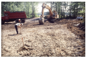
In preparing for excavation, the area to be removed should be marked with stakes. See Figure 1. The stakes should be a slight distance away from the area to be removed so that they are not removed during excavation. The stakes should be marked to establish grades, or have string lines pulled and tied to them. Slopes should be a minimum of 1.5%. In the case of roads, the minimum longitudinal slope should be 1% with a minimum cross slope of 2%. Grade stakes should be checked periodically during the job to be sure that they have not been disturbed.
Excavating, Drainage and Compacting the Soil Subgrade
During and after excavation, the soil should be inspected for organic materials or large rocks. If organic materials, roots, debris, or rocks remain, they should be removed and replaced with clean, compacted aggregate backfill material. Freestanding water saturating the soil should be removed. After it is removed, low, wet areas can be stabilized with a layer of crushed stone and/or cement.
Typical 4 in. (100 mm) diameter perforated drainage pipes surrounded with minimum 3 in. (75 mm) of No. 57 or similar open-graded stone is wrapped in woven or non-woven geotextile as specified by the designer. The surface of the stone is even with the top of the compacted soil subgrade. The stone and geotextile pipe assembly is placed along the pavement perimeter to remove excess water in the subgrade soil and base. The perforated pipe should be sloped and directed to outlets at the sides or ends of the pavement. The pipe outlets should be covered with screens to prevent animal ingress. Drain pipes are recommended in clay soils or other slow draining soils subject to vehicular traffic. Soil subgrade drainage extends pavement performance to the extent that the small additional investment is returned many times in additional pavement service years.
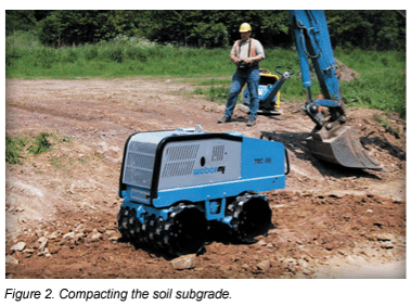
Compaction of the soil subgrade is critical to the performance of interlocking concrete pavements. See Figure 2. Adequate compaction will minimize settlement. Compaction should be at least 98% of standard Proctor density as specified in ASTM D698. However, modified Proctor density (ASTM D1557) is preferred, especially for areas under constant vehicular traffic. This compaction standard may not be achievable in extremely saturated or very fine soils. Stabilization of the soil subgrade may be necessary in these situations.
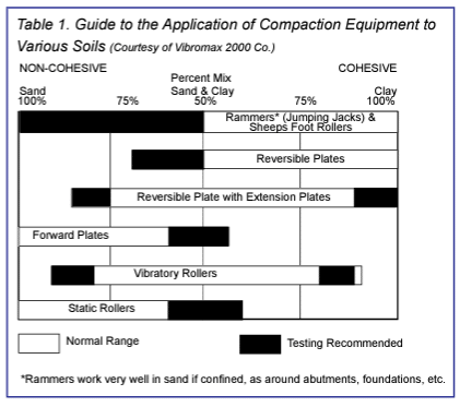
Compaction equipment varies with the type of subgrade soil. Manufacturers of compaction equipment can provide guidance on which machines should be applied to various types of soil. Table 1 gives general guidance on applying the right machines to various soil types.
Monitoring soil moisture content is important to reaching the compaction levels described above. Soil moisture and density measurements should be taken to control and verify the degree of compaction. Soil should be moist, without visible signs of water, stick together as a ball when squeezed by hand and break into a few pieces when dropped from 6 to 12 inches as indicated in CMHA Concreter Paver Course Manual. The moisture content and compacted density of the subgrade soil should be checked for compliance to specifications before installing geotextiles.
Applying Geotextiles (Optional)
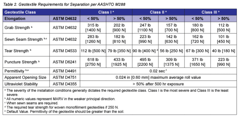
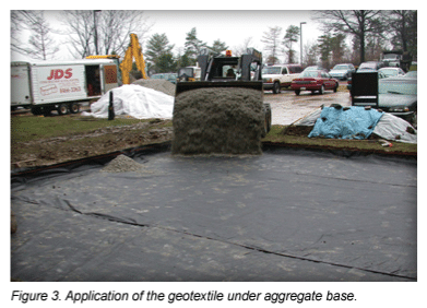
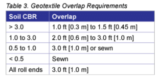
Geotextile may be used in areas where soil remains saturated part of the year, where there is freeze and thaw, or over clay and moist silty subgrade soils. See Figure 3. As a separation layer, geotextiles prevent the migration of soil into the aggregate base under loads, especially when saturated, thereby reducing the likelihood of rutting. When geotextiles are used they preserve the load bearing capacity of the base over a greater length of time than placement without them. Woven or non-woven fabric may be used under the base with a maximum apparent opening size of 0.60 mm as testing using ASTM D4751. Table 2 lists minumum requirements of geotextiles for soil separation. These requirements are from AASHTO M288 Standard Specification for Geotextile Specification for Highway Applications (AASHTO 2015). The minimum down slope overlap should be at least 12 in. (300 mm). Overlap requirements for low strength subgrades are detailed in Table 3.
When the fabric is placed in the excavated area, it should be turned up along the sides of the opening, covering the sides of the base layer. There should be no wrinkles on the bottom. When the aggregate is dumped on the fabric, the tires from trucks should be kept off the fabric to prevent wrinkling.
Spreading and Compacting the Subbase and/or Base Aggregates
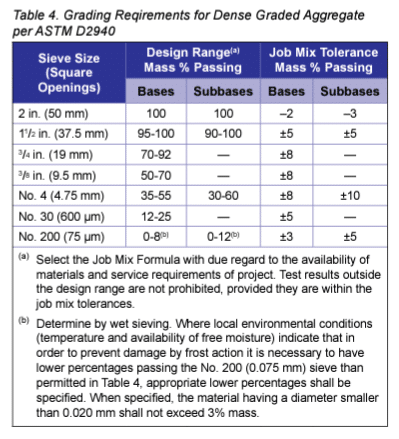
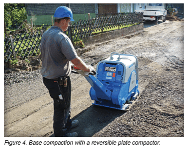
Specifications typically used by cities, states, or provinces for aggregate base materials under flexible asphalt pavements are adequate for interlocking concrete pavements. If no specifications are available use the recommended grading for the aggregate base shown in Table 4. Spread and compact the base in 4 to 6 in. (l00 to 150 mm) lifts using 7,000 lbf (31 kN) reversible plate compactors. Thinner lifts will be required for compactors in the 5,000 lbf (22 kN) range. High force compaction equipment can compact thicker lifts. Consult with compaction equipment manufacturer for guidance. Frozen base material should not be installed, nor should material be placed over a frozen soil subgrade.
Recycled concrete aggregates (RCA) used with interlocking concrete pavement in vehicular areas should be from crushed sources certified by a state or provincial department of transportation as meeting specifications for gradation and hardness. These typically include limits on the percent passing the No. 200 (0.075 mm) sieve (generally <12%) and abrasion durability tests such as Los Angeles abrasion resistance or micro-Deval loss. No more than 50% RCA mixed with nonrecycled (quarried/crushed) dense-graded aggregates are recommended for vehicular applications. For pedestrian interlocking concrete pavements, up to 100% RCA can be used. However, there is an increased risk of efflorescence passed to the concrete paver surface. While not affecting structural performance, efflorescence may be unsightly and difficult to remove. Recycled asphalt materials should follow the aforementioned guidelines.
The thickness of the base is determined by traffic, soil type, subgrade soil drainage and moisture, and climate. Sidewalks, patios and pedestrian areas should have a minimum base thickness (after compaction) of 4 in. (100 mm) over well-drained soils. Residential driveways on well-drained soils should be at least 6 in. (150 mm) thick. In colder climates, continually wet or weak soils will require that bases be thicker.
Local, state or provincial engineering standards for base thickness can be applied to streets constructed with interlocking concrete pavers. Non freeze-thaw areas with well-drained soils should have at least a 6 in. (150 mm) thick base. Minimum base thicknesses for residential streets are 8 to 10 in. (200 to 250 mm). Greater thicknesses are often used in regions with numerous freeze-thaw cycles, expansive soils, or very cold climates. A qualified civil engineer familiar with local soils and traffic conditions should be consulted to determine the appropriate base thickness for streets and heavy-duty, industrial pavements.
Many localities determine base thickness with the 1993 Guide for the Design of Pavement Structures published by the American Association of State Highway and Transportation Officials (AASHTO). The AASHTO procedure calculates the structural number (SN) of the strength coefficients of each base and pavement layer. The SN is determined by assessing the traffic loads, soils, and environmental factors (e.g., drainage, freeze-thaw). The layer coefficient recommended for 31/8 in. (80 mm) thick pavers on 1 in. (25 mm) bedding sand is 0.44 per inch (25 mm), i.e., the SN = 41/8 x 0.44 = 1.82. Base thicknesses can be readily determined by using the charts in Tech Note PAV-TEC-004 Structural Design of Interlocking Concrete Pavement for Roads and Parking Lots or CMHA Structural Design Software. This software is available for free download on www. masonryandhardscapes.org.
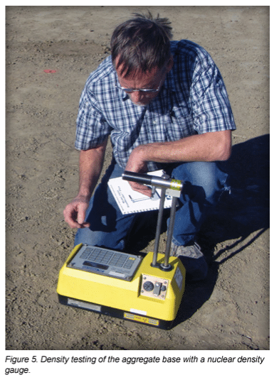
Like compaction of the soil subgrade, adequate compaction of the base is critical to minimizing settlement of interlocking concrete pavements. See Figure 4. Special attention should be given to achieving compaction standards adjacent to edge restraints, catch basins and utility structures. When spread and compacted, the aggregate base should be at its optimum moisture. Bases for pedestrian areas and residential driveways should be compacted a minimum 98% of standard Proctor density. For vehicular areas, compaction should be at least 98% of modified Proctor density as determined by ASTM D1557, or AASHTO T180. While the highest percentage compaction (100%) is preferred, it may not be achievable on weak or saturated soils. Density measurements of the compacted base should be made with a nuclear density gauge or other methods approved by the local, state or provincial transportation department. See Figure 5. Unless otherwise specified, the compacted thickness of individual lifts should be +3/4 in. to –1/2 in. (+19 mm to –13 mm). Maintaining consistent lift thickness during compaction will help achieve consistent density. Variation in final base surface elevations should not exceed ±3/8 in. (± 10 mm) when tested with a 10 ft. (3 m) straightedge.
The finished surface of a compacted aggregate base should not allow bedding sand to migrate into it. If the surface will allow ingress of bedding sand, a choke course of fine material can be spread and compacted into the surface, or a bitumen tack coat can be applied. The surface of the base course and its perimeter around the edge restraints should be inspected for areas that might allow sand to migrate after installation. Such locations can be joints in curbs, around utility structures or catch basins. These areas should be covered with a geotextile fabric to prevent loss of the bedding sand.
Constructing Edge Restraints
Edge restraints are a key part of interlocking concrete pavements. By providing lateral resistance to loads, they maintain continuity and interlock among the paving units. Aluminum, steel, plastic, or concrete are typical edge restraints. Consult CMHA Tech Note PAV-TEC-003 on edge restraints for recommendations on applications and construction. Edge restraints must be set at the correct level, especially if the tops of the restraints are used for screeding the bedding sand. Their elevations should be checked prior to placing the sand and pavers. A minimum of 1 in. (25 mm) vertical restraining surface should be in contact with the side of the paver to adequately restrain it. For heavy duty application a greater restraining surface may be warranted. Edge restraints are typically installed before the bedding sand and pavers are laid. However, some restraints can be secured into the base as the laying progresses.
Placing and Screeding the Bedding Sand
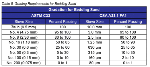
Bedding sand under concrete pavers should conform to ASTM C33 or CSA A23.1. This material is often called concrete sand. Masonry sand for mortar should never be used for bedding, nor should limestone screenings or stone dust. The bedding sand should have symmetrical particles, generally sharp, washed, with no foreign material. Waste screenings and stone dust should not be used, as they often do not compact uniformly and can inhibit lateral drainage of moisture in the bedding layer. CMHA Tech Note PAV-TEC-017—Bedding Sand Selection for Interlocking Concrete Pavements in Vehicular Applications provides additional guidance on selecting bedding sand and gradations including limits on material passing the No. 200 (0.075 mm) seive. See Table 5.
Bedding sand should be spread and screeded to an uncompacted nominal 1 in. (25 mm) thickness. Frozen or saturated sand should not be installed. If there is an uneven base (due to inconsistent compaction or improper grading), the bedding sand should not be used to compensate for it. Over time, unevenness in the bedding sand will reflect through to the surface. Uneven areas on the base surface must be made even prior to placing the bedding sand.
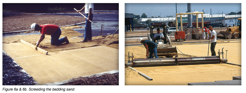
Once the base is complete, screed pipes or rails are placed on it and the bedding sand spread over them. The sand is screeded or smoothed across the pipes with a straight and true strike board. See Figure 6. Screed pipes are removed and the resulting void filled with bedding sand. After the sand is screeded it should not be disturbed. Sufficient sand is placed and screeded to stay ahead of the placed pavers. Powered screeding machines that roll on rails and asphalt spreading machines adapted for screeding sand have been successfully used on larger installations to increase productivity.
Placing the Concrete Pavers
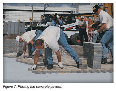
Concrete pavers can be placed in many patterns depending on the shapes. Herringbone patterns (45 or 90 degree) are recommended in all street applications, as these interlocking patterns provide the maximum load bearing support, and resist creep from starting, braking and turning tires. See Figure 7. CMHA takes a conservative approach by not recognizing differences among paver shapes with respect to structural and functional performance. Certain manufacturers may have materials and data that discuss the potential benefits of shapes on functional and structural performance in vehicular applications. Chalk lines snapped on the bedding sand or string lines pulled across the surface of the pavers are used as a guide to maintain straight joint lines. Buildings, concrete collars, inlets, etc., are generally not straight and should not be used for establishing straight joint lines.
Paving units arrive at the job site packaged in bundles that are often strapped and/or wrapped to a wooden shipping pallet. Paving units should be taken from 3 or 4 bundles and not from a single one. Mixing the pavers ensures a visually consistent blend of the colors. If there’s only one color of pavers on the job, installing pavers from several bundles at the same time will diminish the appearance of slight variations in that color.
Joint widths between the pavers should be consistent and be between 1/16 and 3/16 in. (2 and 5 mm). Most pavers are made with spacer bars on their sides. These maintain a minimum joint width, allowing the sand to enter between each unit. Pavers without spacers are generally not placed snug against each other since string lines guide consistent joint spacing.
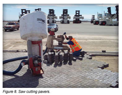
Cut pavers should be used to fill gaps along the edge of the pavement. Pavers are cut with a double bladed splitter or a masonry saw. See Figure 8. A saw gives a smooth cut. All saws should have equipment to reduce the dust created, since it is know to contain high level of respirable crystaline silica. Gaps greater than 3/8 in. (10 mm) should be filled with cut pavers. For street applications do not cut pavers to less than 1/3 their original size. Instead fill voids with two cut pavers.
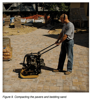
After an area of pavers is placed, it should be compacted with a vibrating plate compactor, which should be capable of exerting a minimum of 5,000 lbf. (22 kN) of centrifugal compaction force and operate at 75-90 hertz. See Figure 9. At least two passes should be made across the pavers to seat the pavers in the bedding sand and force it into the joints at the bottom of the pavers.
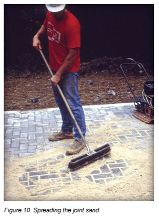
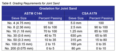
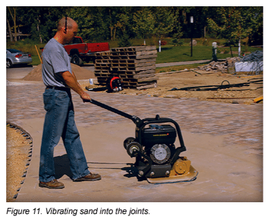
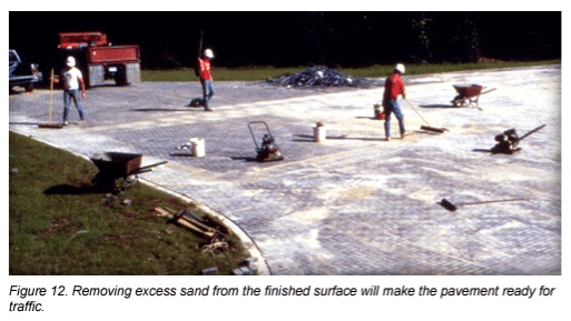
Dry joint sand is spread into the joints and the pavers compacted again until the joints are full. See Figures 10 and 11. This may require two or three passes of the plate compactor. If the sand is wet, it should be spread on a clean, hard surface to dry before being spread on the pavers and compacted into the joints. Joint sand may be finer than the bedding sand to facilitate filling of the joints like a sand meeting ASTM C144 or CSA A179 requirements. See Table 6. Bedding sand also can be used to fill the joints, but it may require extra effort in spreading and compacting. Compaction should be within 6 ft (2 m) of an unrestrained edge or laying face. All pavers within 6 ft (2 m) of the laying face should have the joints filled and be compacted at the end of each day. Excess sand is then removed. See Figure 12. The remaining uncompacted edge can be covered with a waterproof covering if there is a threat of rain. This will prevent saturation of the bedding sand, minimizing removal and replacement of the bedding sand and pavers.
Final surface elevations should not vary more than +3/8 in. (+10 mm) under a 10 ft (3 m) straightedge, unless otherwise specified. Bond or joint lines should not vary ±1/2 in. (13 mm) over 50 ft (15 m) from taut string lines. The top of the pavers should be 1/8 to 3/8 in. (3 to 10 mm) above adjacent catch basins, utility covers, or drain channels, with the exception of areas required to meet ADA design guideline tolerances. Lippage between individual pavers should be a maximum 1/8 in. (3 mm) for pedestrian access routes. The top of the installed pavers may be 1/8 to 1/4 in. (3 to 6 mm) above the final elevations to compensate for possible minor settling. A small amount of settling is typical of all flexible pavements. Optional sealers or joint sand stabilizers may be applied. Using stabilized sand may have advantages in areas prone to joint sand loss. See CMHA Tech Note PAV-TEC-005 Cleaning, Sealing and Joint Sand Stabilization of Interlocking Concrete Pavement for further guidance.
CMHA Tech Note PAV-TEC-009–A Guide Specification for the Construction of Interlocking Concrete Pavement helps translate construction methods and procedures described here into a construction document. Tech Note PAV-TEC-009 provides a template for developing project-specific materials and installation specifications for the bedding and joint sand, plus the concrete pavers. Consult the Construction Tolerances and Recommendations for Interlocking Concrete Pavements for the list of recommended tolerances. Additional guide specifications and detail drawings for varioius applications are available at www.masonryandhardscapes.org as well as CMHA Tech Notes. Other CMHA Tech Notes and technical manuals should be referenced for information on design, detailing, construction and maintenance.
Maintenance of Interlocking Concrete Pavement
Occasionally interlocking concrete pavements will require maintenance for them to deliver peak performance. Refer to Tech Note PAV-TEC-006–Operation and Maintenance Guide for Interlocking Concrete Pavement for information on preventative maintenance, identifying and remedying aesthetic and structural distresses and best practices for the disassembly and reinstatement of interlocking concrete pavement.
Resources
- Refer to the latest published ASTM and CSA standards and CMHA Tech Notes.
- ASTM–American Society for Testing and Materials International, Conshocken, PA. www.astm.org
- CSA–Canadian Standards Association, Rexdale, ON. www.csagroup.org
- CMHA– Concrete Masonry and Hardscapes Association, Herndon VA. www.MasonryandHardscapes.org
- ASCE 2016– American Society of Civil Engineers, Structural Design of Interlocking Concrete Pavements for Municipal Streets and Roadways. Reston, VA. www. ASCE.org
- CSA–CAASHTO 2015–American Association of State Highway and Transportation Officials, Standard Specification for Geotextile Specification for Highway Applications M288-15, Washington, D.C., 2006
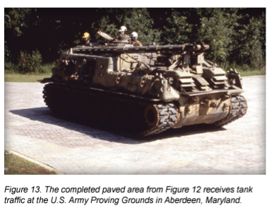
Figures 1, 6a, 7, 10, 12, 13 are courtesy of the Waterways Experiment Station, U.S. Army Corps of Engineers. Figure 5 is courtesy of the Portland Cement Association.