INTRODUCTION
Segmental retaining walls (SRWs) are gravity retaining walls which can be classified as either: conventional (structures that resist external destabilizing forces due to retained soils solely through the self-weight and batter of the SRW units); or geosynthetic reinforced soil SRWs (composite systems consisting of SRW units in combination with a mass of reinforced soil stabilized by horizontal layers of geosynthetic reinforcement materials). Both types of SRWs use dry-stacked segmental units that are typically constructed in a running bond configuration. The majority of available SRW units are dry-cast machine-produced concrete.
Conventional SRWs are classified as either single depth or multiple depth. The maximum wall height that can be constructed using a single depth unit is directly proportional to its weight, width, unit-to-unit shear strength and batter for any given soil and site geometry conditions. The maximum height can be increased by implementing a conventional crib wall approach, using multiple depths of units to increase the weight and width of the wall.
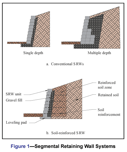
Reinforced soil SRWs utilize geosynthetic reinforcement to enlarge the effective width and weight of the gravity mass. Geosynthetic reinforcement materials are high tensile strength polymeric sheet materials. Geosynthetic reinforcement products may be geogrids or geotextiles, although most SRW construction has used geogrids. The geosynthetic reinforcement extends through the interface between the SRW units and into the soil to create a composite gravity mass structure. This enlarged composite gravity wall system, comprised of the SRW units and the reinforced soil mass, can provide the required resistance to external forces associated with taller walls, surcharged structures or more difficult soil conditions.
Segmental retaining walls afford many advantages, including design flexibility, aesthetics, economics, ease of installation, structural performance and durability. To function as planned, SRWs must be properly designed and installed. Inspection is one means of verifying that the project is constructed as designed using the specified materials.
This Tech Note is intended to provide minimum levels of design and construction inspection for segmental retaining walls. The inspection parameters follow the Design Manual for Segmental Retaining Walls (ref. 1) design methodology. This information does not replace proper design practice, but rather is intended to provide a basic outline for field use by installers, designers and inspectors.
INSPECTION
Many masonry projects of substantial size require a quality assurance program, which includes the owner’s or designer’s efforts to require a specified level of quality and to determine the acceptability of the final construction. As part of a quality assurance program, inspection includes the actions taken to ensure that the established quality assurance program is met. As a counterpart to inspection, quality control includes the contractor’s or manufacturer’s efforts to ensure that a product’s properties achieve a specified requirement. Together, inspection and quality control comprise the bulk of the procedural requirements of a typical quality assurance program.
SRW UNIT PROPERTIES
SRW units comply with the requirements of ASTM C1372, Standard Specification for Dry-Cast Segmental Retaining Wall Units (ref. 2), which governs dimensional tolerances, finish and appearance, compressive strength, absorption, and, where applicable, freeze-thaw durability. These requirements are briefly summarized below. A more thorough discussion is included in SRW-TEC-001-15, Segmental Retaining Wall Units (ref. 3). The user should refer to the most recent edition of ASTM C1372 to ensure full compliance with the standard.
- Dimensional tolerances: ±1/8 in. (3.2 mm) from the specified standard overall dimensions for width, height and length (waived for architectural surfaces).
- Finish and appearance:
- free of cracks or other defects that interfere with proper placement or significantly impair the strength or permanence of the construction (minor chipping excepted),
- when used in exposed construction, the exposed face or faces are required to not show chips, cracks or other imperfections when viewed from at least 20 ft (6.1 m) under diffused lighting,
- 5% of a shipment may contain chips 1 in. (25.4 mm) or smaller, or cracks less than 0.02 in. (0.5 mm) wide and not longer than 25% of the nominal unit height,
- the finished exposed surface is required to conform to an approved sample of at least four units, representing the range of texture and color permitted
- Minimum net area compressive strength: 3,000 psi (20.7 MPa) for an average of three units with a minimum of 2,500 psi (17.2 MPa) for an individual unit. When higher compressive strengths are specified, the tested average net area compressive strength of three units is required to equal or exceed the specified compressive strength, and the minimum required single unit strength is:
- the specified compressive strength minus 500 psi (3.4 MPa) for specified compressive strengths less than 5,000 psi (34.4 MPa), or
- 90% of the specified compressive strength when the specified compressive strength is 5,000 psi (34.4 MPa) or greater.
- Maximum water absorption:
- 18 lb/ft3 (288 kg/m3) for lightweight units (< 105 pcf (1,680 kg/m3))
- 15 lb/ft3 (240 kg/m3) for medium weight units (105 to less than 125 pcf (1,680 to 2,000 kg/m3))
- 13 lb/ft3 (208 kg/m3) for normal weight units ( > 125 pcf (2,000 kg/m3 or more))
- Freeze-thaw durability—In areas where repeated freezing and thawing under saturated conditions occur, freeze- thaw durability is required to be demonstrated by test or by proven field performance. When testing is required, the units are required to meet the following when tested in accordance with ASTM C 1262, Standard Test Method for Evaluating the Freeze-Thaw Durability of Manufactured Concrete Masonry Units and Related Concrete Units (ref. 4):
- weight loss of each of five test specimens at the conclusion of 100 cycles < 1% of its initial weight; or
- weight loss of each of four of the five test specimens at the end of 150 cycles < 1.5 % of its initial weight.
REFERENCES
- Design Manual for Segmental Retaining Walls (Third Edition), TR 127B. Concrete Masonry & Hardscapes Association, 2009.
- Standard Specification for Dry-Cast Segmental Retaining Wall Units, ASTM C1372. ASTM International, Inc., 2017.
- Segmental Retaining Wall Units, SRW-TEC-001-15, Concrete Masonry & Hardscapes Association, 2008.
- Standard Test Method for Evaluating the Freeze-Thaw Durability of Dry Cast Segmental Retaining Wall Units and Related Concrete Units, ASTM C1262. ASTM International, Inc., 2017.
- International Building Code. International Code Council, 2012.
- Segmental Retaining Wall Installation Guide, SRW- MAN-003-10, Concrete Masonry & Hardscapes Association, 2010.
Design Checklist
Construction Checklist