INTRODUCTION
Segmental retaining walls (SRWs) are gravity retaining walls that rely primarily on their mass (weight) for stability. The system consists of concrete masonry units which are placed without the use of mortar (dry stacked), and which rely on a combination of mechanical interlock, unit to unit interface friction or shear capacity and mass to prevent overturning and sliding. The units may also be used in combination with horizontal layers of soil reinforcement which extend into the backfill to increase the effective width and weight of the gravity mass.
Segmental retaining walls are considered flexible structures, so the footing does not need to be placed below the frost line provided there is sufficient foundation bearing capacity. SRW units are manufactured in conformance with industry standards and specifications to assure that units delivered to a project are uniform in weight, dimensional tolerances, strength, and durability—features not necessarily provided in site cast materials.
SYSTEM ADVANTAGES
Segmental retaining walls afford many advantages; among which are design flexibility, aesthetics, economics, ease of installation, performance and durability.
Design flexibility: The SRW system is composed of units whose size and weight makes it possible to construct walls in the most difficult of locations. Curves and other unique layouts can be easily accommodated. Segmental retaining walls have the ability to function equally well in large-scale applications (highway walls, bridge abutments, erosion control, parking area supports, etc.) as well as smaller residential landscape projects.
Aesthetics: Since SRW units are available in a variety of sizes, shapes, textures and colors, segmental retaining walls provide designers and owners with both an attractive and a structurally sound wall system.
Economics: SRWs provide an attractive, cost effective alternative to conventional cast-in-place concrete retaining walls. Savings are gained because on-site soil can usually be used eliminating costs associated with importing fill and/or
removing excavated materials, and because there is no need for extensive formwork or heavy construction equipment.
Ease of installation: Most SRW units can be placed by a single construction worker. The dry stack method of laying units without mortar allows erection of the wall to proceed rapidly.
Performance: Unlike rigid retaining wall structures, which may display cracks when subjected to movement, the flexible nature of segmental retaining walls allows the units to move and adjust relative to one another without visible signs of distress.
Durability: Segmental units are manufactured of high compressive strength, low absorption concrete which helps make them resistant to spalling, scour, abrasion, the effects of freeze-thaw cycles, rot, and insect damage.
WALL TYPES
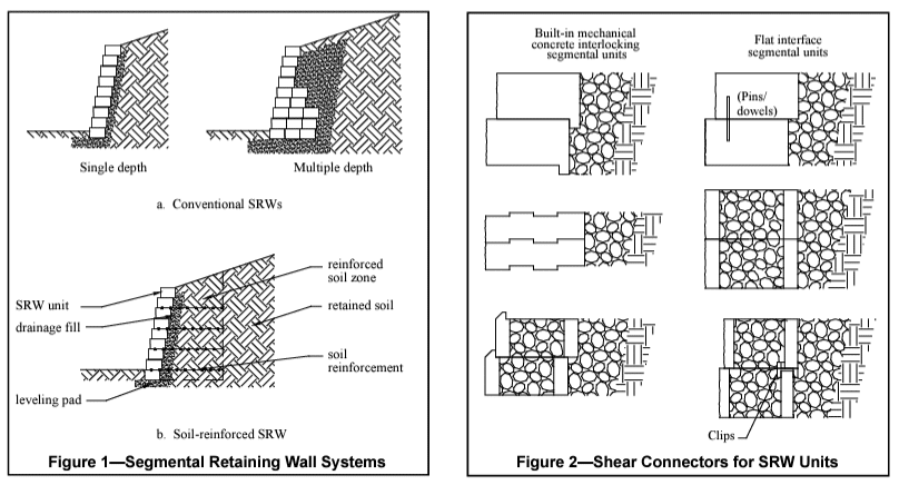
Segmental retaining walls can be designed as either conventional or as reinforced soil, as illustrated in Figure 1. The structural capacity of the SRW system will vary with the SRW unit size, shape, batter, etc. Manufacturers recommendations should be followed regarding the capacity of their particular system for the soil loads under consideration.
Conventional
Conventional SRWs are constructed with either single or multiple depths of units. For stability, the conventional SRW structure must have sufficient mass to prevent both sliding at the base and overturning about the toe of the structure. Since the system consists of individual units dry stacked one atop another, shear capacity is an important component to assure that the units act together as a coherent mass.
Shear capacity provides a means of transferring lateral forces from each course to the succeeding course. This is provided by the frictional resistance between SRW units; and in the form of “keys” or leading/trailing lips which are an integral part of the units; or by the use of clips, pins, or compacted columns of aggregate placed in the open cores (Figure 2).
Structural stability of the SRW can be increased by increasing the wall batter. Batter is achieved through the setback between SRW units from one course to the next. In most cases, the batter is controlled by the location of shear pins or leading/trailing lips (Figure 2), however, some systems allow some adjustment to the batter.
Taller walls can also be achieved by using multiple depths of units, shown in Figure 1a. The multiple depths of units increase the weight of the wall system and provide a more stable base and greater resistance to soil pressures.
Reinforced Soil
Reinforced soil walls should be specified when the maximum height for conventional gravity walls is exceeded or when lower structures are surcharged by sloping backfills, live loads, and/or have poor foundations. A reinforced soil SRW is designed and constructed with multiple layers of soil reinforcement placed between the SRW courses and extending back into the soil behind the wall at designated heights and lengths as shown in Figure 1b. The geosynthetic reinforcement and the soil in the reinforced zone acts as a composite material, effectively increasing the size and weight of the gravity wall system.
SYSTEM COMPONENTS
The basic elements of each segmental retaining wall system are the foundation soil, leveling pad, segmental retaining wall units, retained soil, drainage fill, and, for reinforced soil SRWs, the soil reinforcement.
Foundation soil: The foundation soil supports the leveling pad and the reinforced soil zone of a soil-reinforced SRW system.
Leveling pad: The leveling pad is a level surface, consisting of crushed stone or unreinforced concrete, which distributes the weight of the SRW units over a wider area and provides a working surface during construction. The leveling pad typically extends typically 6 in. (152 mm) from the toe and heel of the lowermost SRW unit and is at least 6 in. (152 mm) thick.
Segmental retaining wall units: Segmental retaining wall units are concrete masonry units that are used to create the mass necessary for structural stability, and to provide stability, durability, and visual enhancement at the face of the wall.
Retained soil: Retained soil is the undisturbed soil for cut walls or the common backfill soil compacted behind infill soils.
Gravel fill: Gravel fill is free-draining granular material placed behind the facing units to facilitate the removal of incidental groundwater and minimize buildup of hydrostatic pressure, and to allow compaction to occur without large forces acting on the SRW units. In units with open cores, gravel can be used to increase the weight and shear capacity. In some cases, a geotextile filter is installed between the gravel fill and the infill to protect the gravel from clogging. The gravel fill should extend a minimum of 12 in. (305 mm) behind the SRW units regardless of the type.
Reinforced soil: Reinforced soil is compacted structural fill used behind soil-reinforced SRW units which contains horizontal soil reinforcement. A variety of geosynthetic soil reinforcement systems are available.
DESIGN CONSIDERATIONS
Typical designs and specifications for segmental retaining walls should be prepared by a designer who has technical knowledge of soil and structural mechanics. Each SRW unit manufacturer can provide design information tailored to that product, which will indicate the wall heights and design conditions when an SRW should be designed by a qualified engineer. In addition, SRW systems should be designed by a qualified engineer when:
- structures will be subject to surcharge loads;
- walls will be subjected to live loads;
- walls will be founded on poor foundations; or
- the nature of the design conditions requires special consideration.
The following general site information should be provided:
- a wall profile, including the grade at the top and bottom of the wall, the physical elevation of the top and bottom of the structure to be retained, and the variation of the design section along the height of the wall,
- a description of the infill, foundation, and retained soils,
- a wall plan, which should include geometry for curved wall lengths and the proximity to any existing or proposed surcharges, structures, or utilities that may affect wall construction or performance. Ends of the wall should be designed with consideration of how surface water flow is directed around the wall ends to prevent erosion.
This data should be sufficiently accurate to develop an efficient, safe, and cost-effective structural design.
GUIDE SPECIFICATIONS
Guide specifications for a materials specification (product/ method) for segmental retaining walls is available in standard Construction Specifications Institute (CSI) format in the Design Manual for Segmental Retaining Walls, (ref. 1). Gravel fill is free-draining granular material placed behind the facing units to facilitate the removal of incidental groundwater and minimize buildup of hydrostatic pressure, and to allow compaction to occur without large forces acting on the SRW units. In units with open cores, gravel can be used to increase the weight and shear capacity. In some cases, a geotextile filter is installed between the gravel fill and the infill to protect the gravel from clogging. The gravel fill should extend a minimum of 12 in. (305 mm) behind the SRW units regardless of the type.
The traditional product/method specification, designating materials and installation requirements, stipulates that a site- specific design be performed by the engineer. Designs should be such that specified SRW and soil reinforcement properties can be met by a number of manufacturers, and should include properties of the on-site soil. SRW and soil reinforcement properties are then specified as the minimum properties that must be met.
In addition, the specification for SRW units may be found in ASTM C1372, Standard Specification for Segmental Retaining Wall Units (ref. 3).
CONSTRUCTION
The success of any segmental retaining wall installation depends on complete and accurate field information, careful planning and scheduling, the use of specified materials, proper construction procedures, and inspection.
It is good practice to have the retaining wall location verified by the owner’s representative. Existing and proposed finish grades shown on the drawings should be verified to ensure the planned design heights are in agreement with the topographic information from the project grading plan. The contractor should coordinate the delivery and storage of materials at the site to ensure unobstructed access to the work area and availability of materials. Materials delivered to the site should be accompanied by the manufacturer’s certification that the materials meet or exceed the specified minimum requirements.
Construction occurs in the following sequence:
- excavation and leveling pad construction
- setting, leveling, and backfilling base course
- filling unit openings with gravel (if applicable) and placing gravel fill behind the units,
- backfilling from the back of the gravel fill to the end of the reinforcement (if applicable),
- compaction of backfill to the specified density in lifts of 8 in. or less from the front of the wall to the back of the reinforcement (if applicable),
- placement of units, backfilling and compacting in succeeding courses,
- placement of soil reinforcement, securing with the next course of blocks and the gravel fill before tensioning, and backfilling (when required),
- capping and finish grading.
As with any structure used to retain soil, careful attention should be paid to the compaction equipment and procedures used during construction. When compacting soil within 3 ft (0.91 m) of the front face of a wall, compaction tools should be limited to hand operated or walk-behind equipment, preferably a vibrating plate compactor with a minimum weight of 250 lb (113 kg). Reinforced soil behind the 3 ft (0.91 m) area can be compacted with self-propelled riding compaction equipment.
REFERENCES
- Design Manual for Segmental Retaining Walls, Third Edition, Concrete Masonry & Hardscapes Association, 2009.
- Simac, M. R. and J. M. Simac, “Specifying Segmental Retaining Walls”, Landscape Architecture, March 1994.
- Standard Specification for Segmental Retaining Wall Units, ASTM C1372. ASTM International, 2017.