Revised 2022
INTRODUCTION
Crosswalks play an important role in streets by marking pedestrian crossings. With colors, patterns and textures, interlocking concrete pavements (ICP) visually differentiate pedestrian use from vehicular only areas. This difference in appearance provides increased pedestrian safety.
From a structural perspective, crosswalks are a demanding application for any type of pavement. The forces from braking, accelerating and turning vehicles apply additional loads on the crosswalks and on transitions to adjacent pavements. These loads require consideration in crosswalks designed and constructed with ICP. This Tech Note addresses those design, construction and maintenance considerations.
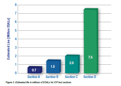
The design recommendations that follow emerged from an Interlocking Concrete Pavement Institute (ICPI) funded research project by the University of Waterloo’s Centre for Pavement and Transportation Technology (CPATT). The study investigated ICP in crosswalk applications and the 2010 report summarizes their performance (Khanal 2010). Headed by Professor Susan Tighe, Ph.D., P. Eng., the three-year accelerated loading study quantified the structural performance of typical ICP crosswalk designs and recommended the maximum expected design life for each assembly. The project evaluated eight crosswalks with four different bases and bedding materials installed at the University of Waterloo Ring Road (See Figure 1) and CPATT test track at the Regional
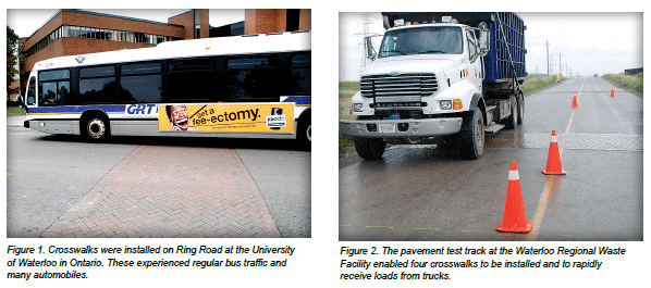
Municipality of Waterloo Waste Management Facility (see Figure 2). The Regional Waste facility experiences heavy loads almost exclusively from truck traffic hauling solid wastes to a landfill. Trucks are weighed while entering this facility which enabled an accurate estimate of loads. The campus Ring Road experienced mostly car and regular bus traffic.
Axle loads vary significantly, from light cars (e.g., 2000 lbs or 9 kN) to fully loaded trucks or buses (i.e., 25,000 lbs or 111 kN). This range is standardized into 18,000 lb (80 kN) equivalent single axle loads (ESALs) and is used by engineers to assess vehicle loads in pavement design. The life of a pavement is in part defined by the number of axle loads applied and the magnitude of those loads, especially from trucks since they damage pavements the most. When the accumulated damage reaches the serviceability limit, i.e., the pavement no longer provides service for which it was intended, the pavement needs major rehabilitation. Damage to ICP is typically rutting.
The amount of damage received by pavement from a vehicle applying one ESAL is equivalent to damage from thousands of automobiles. For example, axle loads from cars are typically 0.0002 ESAL, whereas a loaded truck or bus might be 3 ESALs. Therefore, the amount of damage to a pavement from 15,000 cars would equal the damage from one truck. Defining the expected life of a pavement or its capacity to provide acceptable service while accumulating damage from loads is expressed in ESALs. The greater the ESALs, the longer its life and resistance to rutting. Estimating pavement life in years requires an estimate of the total ESALs given selected pavement materials, subgrade soils, drainage and climate. For further information, CMHA Tech Note PAV-TEC-004–Structural Design of Interlocking Concrete Pavement for Roads and Parking Lots provides an in-depth explanation of ESALs and pavement design.
The CPATT research recommended lifetime ESALs for various crosswalks assemblies. The ESALs were estimated using several analytical tools familiar to pavement engineers. These include the following:
- Periodic condition surveys to determine changes in a pavement condition index (PCI).
- Measuring pavement deflection under wheel loads. Increasing deflection means the pavement structure is failing and not necessarily the wearing course. The amount and rate of increases in deflections can help predict when the pavement will no longer be serviceable. Deflection measurements were taken using a portable falling weight deflectometer (PFWD), and a standard falling weight deflectometer (FWD). The devices apply instantaneous wheel loads while measuring very small deflections in pavement surface. Through modeling and experience with pavement materials, these deflections can be used to predict pavement life expressed as ESALs. The FWD also helped determine the amount of load transfer from the pavers to the concrete headers constructed to restrain the pavers.
- Moisture and temperature of bases and soil subgrades
- Rut depth, movement of the bases and soil subgrade measured by strain gauges
Lifetime ESALs were estimated based on three years of loading at these two locations. All interlocking concrete pavers were 3 1/8 in. (80 mm) thick and placed in a 45 degree herringbone pattern. The crosswalks sections were as follows:
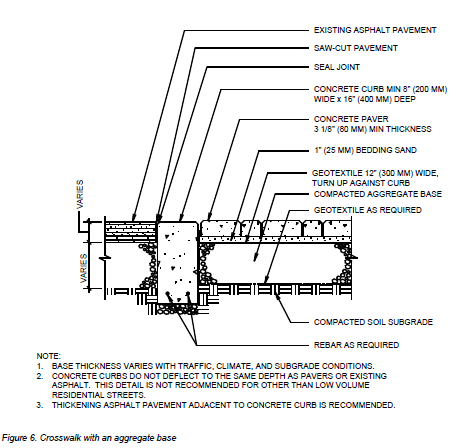
- Section A—Aggregate base, concrete header, sand set Sand-set pavers over an 8 in. (200 mm) thick compacted aggregate base (Ontario Granular A) and a 14 in. (350 mm) thick compacted subbase (Ontario Granular B). The pavers were constrained with concrete headers. A representative detail is provided in Figure 6.
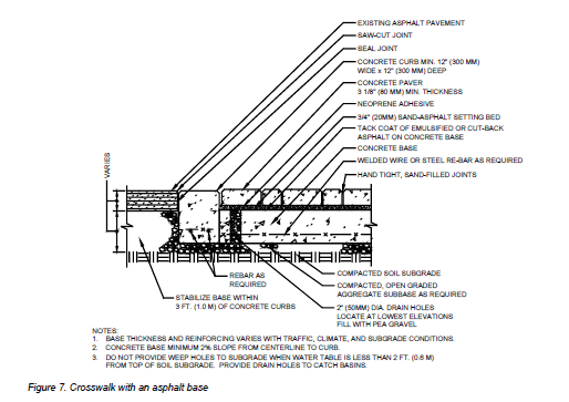
- Section B—Asphalt base, aluminum header, sand set Sand-set pavers over a 4 in. (100 mm) thick asphalt base over 2 in. (50 mm) compacted aggregate base (Ontario Granular A) over an 18 in. (450 mm) thick compacted aggregate base (Ontario Granular B) with an aluminum header against adjacent saw-cut asphalt pavement. A representative detail is provided in Figure 7.
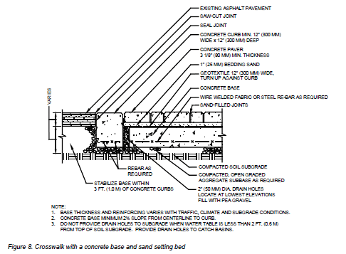
- Section C—Concrete base, concrete header, sand set Sand-set pavers over an 8 in. (200 mm) thick concrete base and a 16 in. (400 mm) thick compacted aggregate subbase (Ontario Granular B) with the pavers constrained by concrete headers. A representative detail is provided in Figure 8.
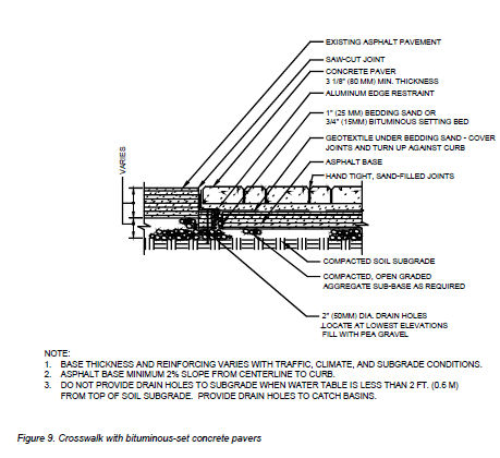
- Section D—Concrete base, concrete header, bituminous set Bituminous set pavers (1 in. or 25 mm thick sand-asphalt bedding layer) over an 8 in. (200 mm) thick concrete base and a 16 in. (400 mm) thick compacted aggregate subbase (Ontario Granular B). The pavers were restrained with concrete headers. A representative detail is provided in Figure 9.
RECOMMENDED DESIGN ESALS FOR EACH SECTION
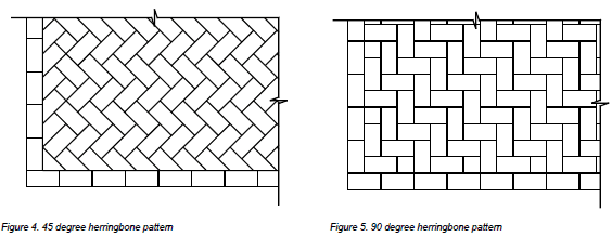
Figure 3 illustrates the estimated lifetime ESALs for each crosswalk assembly.
The conclusion of the study recommend the following design lives for each assembly:
- Section A with concrete headers, aggregate base and sand setting bed has an estimated life of 0.7 million ESALs. This section has the shortest estimated life span and the lowest construction cost. This crosswalk section is appropriate in commercial drives, parking lots, and minor residential collector road applications with mostly automobile traffic.
- Section B with concrete headers, asphalt base and a sand setting bed has an estimated life of 1.5 million ESALs. This crosswalk section is a major collector road with some truck traffic.
- Section C with concrete headers, concrete base and a sand setting bed has an estimated life of 2 million ESALs. This section is also be appropriate for a major collector road application.
- Section D with concrete headers, concrete base and a bituminous-sand setting bed has an estimated life of 7.5 million ESALs. This section had the highest construction cost, but provided a significantly higher life span when compared to the other sections evaluated. This crosswalk section would be appropriate for arterial road application in urban settings subject to regular bus and truck traffic.
In summary, the research noted that each section functioned as an effective crosswalk with different estimated life spans. Selection should be based on the anticipated traffic loads and a life-cycle cost analysis that considers initial costs and future maintenance.
CROSSWALK DESIGN
AND CONSTRUCTION CONSIDERATIONS
Several design and construction aspects of interlocking concrete pavement (ICP) are also common to all crosswalks. Structural design can be developed using Tech Note PAV-TEC-004– Structural Design of Interlocking Concrete Pavement for Roads and Parking Lots as well as ASCE/ANSI 58-16 Structural Design of Interlocking Concrete Pavements for Municipal Streets and Roadways (ASCE 2016). For crosswalks designed for more than 1.5 million lifetime ESALs, a cement or asphalt- stabilized base should be considered. General guidance on CMHA construction is in Tech Note PAV-TEC-002–Construction of Interlocking Concrete Pavement. Bedding sand selection is a key factor in ICP performance and Tech Note PAV-TEC-017– Bedding Sand Selection for Interlocking Concrete Pavements in Vehicular Applications provides guidance. Crosswalks exposed to more than 1.5 million lifetime ESALs utilizing sand bedding require careful selection and testing of the sand to help ensure durability under truck traffic. Tech Note PAV-TEC-009–Guide Specification for the Construction of Interlocking Concrete Pavement may be useful for developing a project specific specification. These Tech Notes as well as the detail drawings and corresponding guide specification are available at www. masonryandhardscapes.org. In addition, construction should be done by an CMHA Certified Concrete Paver Installer.
Paver Selection—Interlocking concrete pavers used in crosswalk applications should be at least 31/8 in. (80 mm thick) and meet specific requirements for compressive strength, absorption and freeze thaw durability for U.S. applications as specified in ASTM C936 Standard Specification of Solid Concrete Interlocking Paving Units and for Canadian applications per CSA A231.2 Precast Concrete Pavers. A summary of the requirements in each follow:
ASTM C936
- Average compressive strength (ASTM C140): 8,000 psi (55 MPa) with no individual unit under 7,200 psi (50 MPa).
- Average Water Absorption (ASTM C140): 5% with no unit greater than 7%.
- Freeze/Thaw Resistance (ASTM C1645): No greater loss than 225 g/m2 of total surface area after 28 freeze-thaw cycles or no greater loss than 500 g/m2 after 49 cycles. Paver units are immersed in water or 3% saline solution depending on anticipated exposure. Freeze-thaw testing requirements can be waived for applications not exposed to freezing conditions.
CSA A231.2
- Average cube or core compressive strength: 50 MPa with no individual unit under 45 MPa.
- Freeze/Thaw Resistance: average loss of mass no greater than (a) 225 g/m2 of the total surface area of the individual paver after 28 cycles of freezing and thawing; or (b) no greater loss of 500 g/m2 of the total surface area after 49 cycles. Paver units are immersed in 3% saline solution.
Paver Shape and Laying Patterns—CMHA recommends that units subject to vehicular traffic have an aspect ratio (length/ thickness) of no greater than 3:1. This ensures a high level of rotational interlock or resistance to rotational movement of the individual concrete units. CMHA also recommends that interlocking concrete pavers have a plan ratio (length/width) between 2:1 and 3:1 for those subject to vehicular traffic. This allows for placement in herringbone patterns which creates a higher level of interlock throughout the pavement surface. Herringbone patterns exhibit shorter, discontinuous joint lines that allow the paving units to distribute load more widely than other patterns. These are shown in Figures 4 and 5.
To complete these patterns, units are cut at the perimeter. CMHA recommends that cut units exposed to tires be no less than 1/3 of a whole unit in order to help maintain stability. A string course, also called a sailor course, is recommended along the edge restraint to help distribute loads at the perimeter of the crosswalk.
Bedding sand—Bedding sand between the base and the pavers should be hard as practically available. It should be coarse, washed, clean, non-plastic, free from deleterious or foreign matter, symmetrically sub-angular shaped, natural or manufactured from crushed rock. The bedding sand should meet the grading requirements of ASTM C33 and is typically referred to as concrete sand. CMHA does not recommend limestone screenings or stone dust in any interlocking concrete pavement. This material typically has irregularly shaped, weaker particles that often degrade after repeated loading. These materials also have a high percentage of fine material which absorb and hold water. This can lead to surface instability and settlement. CMHA does not recommend mason sand or sand conforming to ASTM C144 for the bedding layer. This sand is too fine and will hold water.
Bedding sand durability is important for crosswalks and other vehicular pavements exposed to high traffic loads, especially truck traffic. ICPI Tech Spec 17–Bedding Sand Selection for Interlocking Concrete Pavements in Vehicular Applications recommends durability evaluation using the Micro-Deval degradation test per ASTM D7428. The maximum recommended loss is 8%. This test is recommended when pavers and sand will be placed over concrete, or asphalt, and subject to traffic over 1.5 million ESAL or a Caltrans Traffic Index of 9.5. If high traffic loads are anticipated and suitable bedding sand cannot be specified, the designer should consider using bitumen-set bedding under the pavers as described later.
Geotextile—ICP installed on a concrete or asphalt base, as shown in Figures 7, 8 and 9, is called an overlay. Overlays that utilize bedding sand, such as in Figure 7 and 8, rely upon it to provide a uniform level surface for the pavers. Curb joints around the perimeter of the rigid base or other structures represent an opportunity to lose bedding sand. These areas must be covered with geotextile to prevent its loss. CMHA recommends using a geotextile strip 12 in. (300 mm) wide to cover continuous joints or geotextile patches 12 in. by 12 in. (300 by 300 mm) over drain holes. If there is a high potential for the base to crack and allow bedding sand loss, it should be covered with geotextile. When selecting a geotextile, criteria should consider the permittivity (ability to allow water to flow through) and the abrasion resistance. Typically a heavier weight non-woven geotextile or woven multi-filament / mono-filament geotextile would be appropriate. The geotextile manufacturer should be consulted for additional advice.
Joint sand—Mason sand conforming to the gradation specified in ASTM C144 is used for jointing sand. Use a material where the largest sieve size easily enters the smallest joints. For example, if the smallest paver joints are 2 mm wide, use sand 2 mm and smaller in particle size. ASTM C33 sand can be used for joint sand but joints generally need to be several millimeters wide, otherwise extra effort may be required in sweeping material and compacting the pavers in order to completely fill the smaller joints.
Drainage—Drainage is an important consideration in the overall design of the crosswalk. The pavement around the crosswalk must direct surface water away from it. If water is allowed to pond or settle on the crosswalk it can penetrate the pavement and possibly overload the internal drainage system. This can lead to saturation of the bedding sand, which may then migrate under load and cause the surface to rut.
Providing a slight slope to the crosswalk surface encourages runoff instead of infiltrating into the ICP system. Typically a minimum slope of 2% is sufficient. The use of sealers or stabilized joint sand can also reduce the amount of water penetrating through the joint sand. At the end of construction, the ICP surface should be between 1/8 in. to 1/4 in. (3 to 6 mm) above adjacent drainage inlets, concrete collars or channels. This helps ensure that any further settlement of the system does not create a depression beside these rigid elements where water will collect and infiltrate.
Designs should consider internal drainage of the system and in particular the bedding layer as no paver surface is completely waterproof. Water can exit bedding sand through drilled weep holes into catch basins or other drainage structures at the bedding sand elevation. Typically a geotextile is used to cover the weep holes to keep the bedding sand from migrating into them. Geotextile should not be used to cover drain holes under bituminous-sand bedding because the heat from the applied bituminous material will typically soften and melt the geotextile.
When constructing a crosswalk with a rigid base like concrete or asphalt as shown in Figures 7, 8 and 9, CMHA recommends that weep holes be cast into or drilled vertically through the base. These holes should be a minimum of 2 in. (50 mm) diameter (in non-bituminous setting bed applications), filled with compacted washed, angular aggregate approximately 1/4 to 3/8 (6 to 9 mm) in size. The weep holes should be covered with a patch of geotextile at least 12 by 12 in. (300 by 300 mm) to prevent bedding sand loss into the weep holes. Drain holes should be placed around the perimeter of the base and at the lowest elevations spaced at a minimum separation of 10 to 15 ft. (3 to 5 m). Weep holes typically convey small amounts of water that can be absorbed by the base and soil subgrade.
However, if the water table is close to the pavement base as in some coastal areas, piping the drain holes to a storm sewer may help prevent the water from rising into the pavement via the weep holes.
BITUMEN-SET CROSSWALK SECTION
This section consists of a concrete base with a concrete header and a 3/4 in. (20 mm) thick sand-asphalt bedding layer, rather than sand, under the concrete pavers. See Figure 9. Construction of base and header structure for this section is almost identical to Figure 8. However, after the concrete base is cured, a tack coat of emulsified asphalt is applied. This is allowed to dry before a 3/4 in. (20 mm) thick layer of bituminous sand is applied and compacted. This layer can be a state or provincial transportation department specification for an asphalt finish layer typical to most roads. Asphalt placement must be done while the mix is hot and in a compactable state.
After the compacted asphalt cools, a thin layer of neoprene- asphalt mastic is applied with a squeege onto the surface and allowed to dry. The pavers are placed on this adhesive. Once placed, the pavers cannot be easily relocated. When the placement of pavers is complete (including cut units), jointing sand is spread to fill the joints and the pavers are compacted. Detailed construction procedures for this assembly and the other types can be found in CMHA Tech Note PAV-TEC-020 Construction of Bituminous-Sand Set Interlocking Concrete Pavement and CMHA guide construction specifications at www. masonryandhardscapes.org.
MAINTENANCE
All pavements require maintenance and it is essential for their long term performance. Below is a list of some distress found in ICP crosswalks that require maintenance.
Subsidence, Settlement—This distress is generally attributed to bedding sand loss. Repair typically requires the removal of the pavers and bedding sand in the subsided area. Discard any damaged paver and bedding sand. Identify the reason for the bedding sand loss, i.e. a joint or crack in the rigid base, loss through a cracked curb, etc. and make suitable repairs. In some cases this may simply mean placing a strip or patch of geotextile to cover an open joint or crack. Reinstate the ICP system as stated below.
Rutting—If water is allowed to saturate the bedding sand layer, the sand may migrate under load. Additionally, as the ICP system approaches the end of its estimated life span ruts will develop in the pavement surface. CMHA recommends that ruts in excess of 3/4 in. (19 mm] should be repaired. Repair typically requires the removal of the pavers and bedding sand. Discard any damaged pavers and bedding sand. Reinstate the ICP system as stated at the end of this section.
Asphalt subsidence—Cracked asphalt pavement leading up to or away from the crosswalk structure can occur. Typically, this is attributed to lower density of compacted aggregate and soil subgrade next to the header in new applications. In retrofit construction, asphalt settlement can occur from disturbing the aggregate base. This can be compounded by infiltration of surface water into the joint between the asphalt and the concrete header. CMHA recommends that the joint between the asphalt and concrete be sealed with an asphalt sealer to limit the surface water allowed to enter the system at this point.
Repair of this distress can include the removal of cracked asphalt. Aggregate base will likely be replaced and it needs to be compacted to a minimum of 98% modified Proctor density to its full depth and the asphalt reinstated. Alternatively, a cement-stabilized base aggregate could be used in place of regular unbound aggregate.
Damaged or cracked pavers—Some pavers may be cracked or damaged over time. These units can be removed and replaced. Use pavers from the original lot if available. Removing the first paver may be difficult depending on the age of the pavement and the level of traffic placed on it. It may be necessary to chisel out the first unit. Removal of a paver installed on a bituminous- sand setting bed may be extremely difficult. A combination of chiseling and heating the asphalt bedding may be necessary. After the damaged units are removed, reinstate the ICP as indicated below.
MAINTENANCE OF INTERLOCKING CONCRETE PAVEMENT
Occasionally interlocking concrete pavements will require maintenance for them to deliver peak performance. Refer to Tech Note PAV-TEC-006: Operation and Maintenance Guide for Interlocking Concrete Pavement for information on preventative maintenance, identifying and remedying aesthetic and structural distresses and best practices for the disassembly and reinstatement of interlocking concrete pavement.
REFERENCES
Refer to the latest published ASTM and CSA standards and CMHA Tech notes.
- ASTM–American Society for Testing and Materials International, Conshocken, PA. www.astm.org
- CSA–Canadian Standards Association, Rexdale, ON. www.csagroup.org
- CMHA-Concrete Masonry and Hardscapes Association, Herndon, VA. www.masonryandhardscapes.org
- ASCE 2016. ASCE/ANSI 58-16 Structural Design of Interlocking Concrete Pavements for Municipal Streets and Roadways, American Society of Civil Engineers, Reston, VA.
- Khanal 2010. Khanal, S., Adhikari, S., and Tighe, S., Interlocking Concrete Crosswalk Research Project, Final Report, Centre for Pavement and Transportation Technology, University of Waterloo, Ontario.