INTRODUCTION
Masonry is often specified because of its aesthetic versatility. Combining masonry units of different size, color and finish provides a virtually limitless palette. Often, exterior concrete masonry walls incorporate clay brick, or concrete masonry is used in clay brick walls as accent bands. The bands add architectural interest to the wall and can also help hide horizontal elements such as flashing and expansion joints. However, combining these two materials within one wythe of masonry requires special detailing due to their different material properties.
In general, all masonry walls should be designed and detailed to accommodate anticipated movement resulting from volume changes in the masonry materials themselves. For example, vertical control joints and horizontal joint reinforcement can be incorporated into concrete masonry walls to control cracking and still allow horizontal shrinkage of the concrete masonry units to occur without introducing undue stress into the wall. Similarly, clay masonry walls incorporate vertical and horizontal expansion joints to allow the clay to expand without distress. When both clay and concrete masonry units are used in the same masonry wythe, detailing is required to accommodate concrete masonry shrinkage and clay masonry expansion occurring side by side. Concrete masonry is a hydraulic cement product and as such requires water for cement hydration, which hardens the concrete. Therefore, concrete masonry units are relatively wet at the time of manufacture and from that time on tend to shrink as the units dry. Conversely, clay masonry units are very dry subsequent to firing during the manufacturing process and then tend to expand as they pick up moisture from the atmosphere and from mortar as they are laid. Without due consideration of these opposing movements, cracking can result. In veneers, the cracking is primarily an aesthetic issue, as any water that penetrates the veneer through cracks between the two materials drains down the cavity and is directed out of the wall via flashing and weep holes.
BANDING DETAILS
When detailing a wall to accommodate movement, the design goal is to allow the movement to occur (as restraint will cause cracking) while providing appropriate support. The recommendations that follow are based on a record of successful performance in many locations across the United States. These can be adjusted as needed to suit local conditions and/or experience.
In general, several strategies are used to accommodate movement. These include movement joints (control joints in concrete masonry and expansion joints in clay masonry); horizontal joint reinforcement to take tension due to concrete masonry shrinkage and help keep any cracks that occur closed; and sometimes horizontal joints to allow longitudinal movement. In veneers, it is particularly important that the band, as well as the wall panel above and below the band be supported by wall ties. Wall ties should be installed within 12 in. (305 mm) of the top and bottom of the band to help ensure the surrounding masonry is adequately supported.
In addition, using a lower compressive strength mortar helps ensure that if cracks do occur, they occur in the mortar joint rather than through the unit. Type N mortar is often specified for veneers, because it tends to be more flexible than other mortar types.
Concrete Masonry Band in Clay Brick Wall
Figure 1a shows a two-course high concrete masonry band in a clay brick exterior wythe of a cavity wall. With this type of construction, the following practices are employed to minimize the potential for cracking.
Horizontal joint reinforcement is placed in the mortar joints above and below the band to take stress from the differential movement in that plane. For bands higher than two courses, joint reinforcement should also be placed within the band itself at a spacing of 16 in. (406 mm) on center vertically. Ideally, the joint reinforcement and ties should be placed in alternate joints so that one does not interfere with placement of the other. Some designers, however, prefer placing joint reinforcement in every bed joint in the concrete masonry band, particularly if the aspect ratio of the band is high. In this case, a tie which accommodates both tie and wire in the same mortar joint should be used, such as a seismic clip type wall tie.
Although the detail in Figure 1a has demonstrated good performance in many areas of the United States, there are locations where use of bond breaks at the top and bottom of the band is preferred (see Figure 1b) A local masonry industry representative should be contacted for further information on which detail has been more successful in a given location.
Figure 1b shows a slip plane incorporated into the interfaces between the concrete and clay masonry to allow unrestrained longitudinal movement between the two materials. This can be accomplished by placing building paper, polyethylene, flashing or a similar material in the horizontal bed joints above and below the band. When hollow masonry units are used for the band, the slip plane below the band should incorporate flashing, so that any water draining down the cores of the band can be directed out of the wall at that point.
When slip planes are used, joint reinforcement should be incorporated into the concrete masonry band. The exposed mortar joint at the top and bottom of the band should be raked back and sealed with an appropriate sealant to prevent water penetration at these joints. Note that this construction is typically more expensive than the detail shown in Figure 1a.
In addition to joint reinforcement, reduced spacing of expansion joints in the wall is recommended to reduce the potential for cracking. Experience has shown that vertical expansion joints in the clay masonry should extend through the concrete masonry band as well, and be placed at a maximum of 20 ft (6.1 m) along the length of the wall. Although concrete masonry construction typically requires control joints rather than expansion joints, control joints should not be used in the concrete masonry band at the expansion joint locations.

Note that local experience may require reducing the expansion joint spacing to 16 ft (4.9 m). If brick vertical expansion joint spacing does exceed 20 ft (6.1 m), consider placing an additional vertical movement joint through the concrete masonry accent band near mid panel with joint reinforcement continuous through that joint. The continuous joint reinforcement in this location helps keep the clay brick above and below the band from cracking as the concrete masonry shrinks.
Bands only one course high must be detailed to incorporate joint reinforcement and wall ties in the joints above and below the band (see Figure 2).

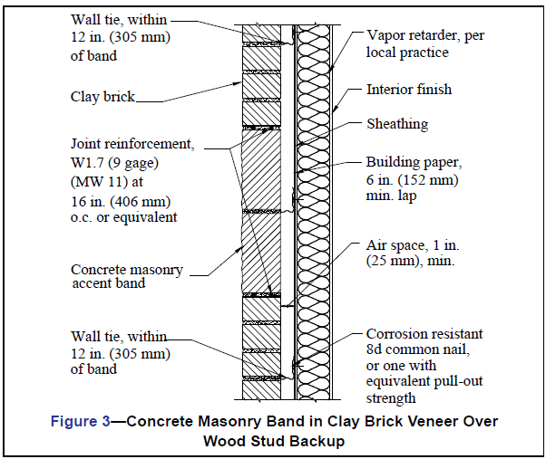
When concrete masonry banding is used over a wood stud backup, similar provisions apply (see Figure 3). It is imperative that joint reinforcement be used in the concrete masonry band, even if it is not used in the surrounding clay brick masonry.
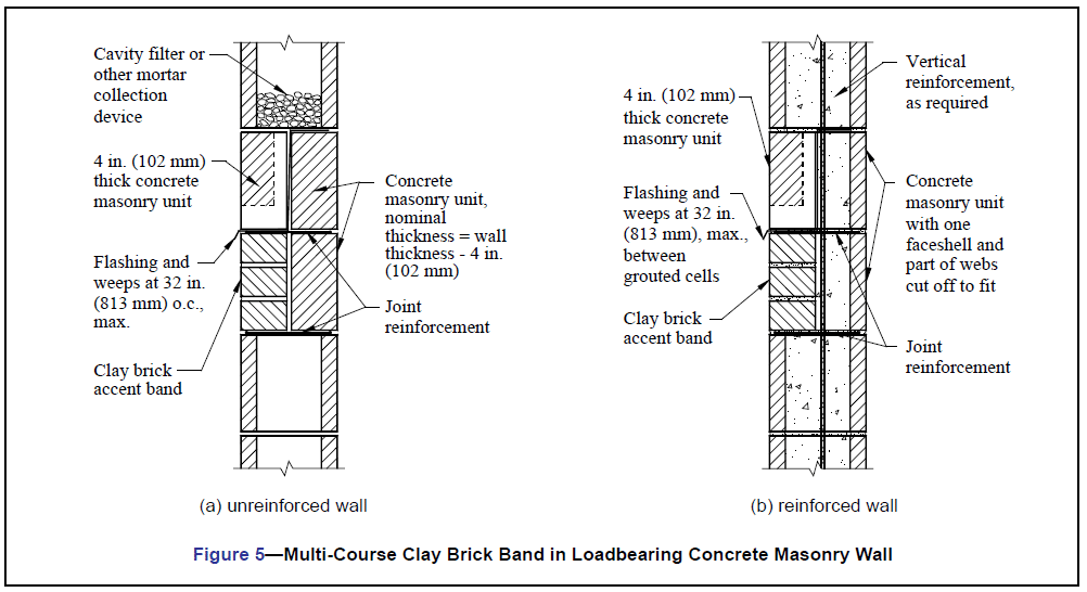
Clay Brick Band in Concrete Masonry Wall
The recommendations to control differential movement for clay brick masonry bands in concrete masonry are very similar to those for a concrete masonry band in clay brick veneer: joint reinforcement above and below the band and wall ties within the band. Seismic clip type wall ties are recommended, as they provide an adjustable wall tie and joint reinforcement in one assembly.
With this construction, it is imperative that the veneer control joint not contain mortar as it goes through effectiveness. Note that although control joints in structural masonry walls must permit free longitudinal movement while resisting lateral or out-of plane shear loads, veneers are laterally supported by the backup and do not require a shear key.
In single wythe construction as shown in Figure 5, flashing and weep holes are used above the accent band to facilitate removal of any water that may accumulate in the wall. The use of two reduced thickness concrete masonry units allows flashing to be placed within the wall without causing a complete horizontal bond break at the flashing.
In reinforced walls (Figure 5b), flashing and weeps are also used. On the wall interior, rather than using reduced thickness units, a full size unit is cut to fit to allow adequate space for the reinforcement and grout.