
INTRODUCTION
Energy efficiency in buildings has become increasingly important. Whether complying with newer energy codes or gaining recognition for sustainable building practices, reducing the overall energy usage in new and existing buildings continues to be a leading consideration for design teams.
Many methods are employed to increase building energy efficiency. One consideration is reducing air leakage through the building envelope. In addition to the negative impact on a building’s energy efficiency (due to the loss of conditioned air via exfiltration and/or the introduction of unconditioned air via infiltration), air leakage in buildings can also impact moisture control, indoor air quality, acoustics and occupant comfort.
Reduced air leakage is one area where masonry walls excel compared to other wall types when proper design criteria are applied. This TEK reviews available information on masonry wall air leakage, reviews the most recent code criteria, presents concrete masonry wall assemblies that meet this criteria, and provides general guidance on improving the control of air leakage in masonry walls.
AIR LEAKAGE
Air leakage consists of air infiltration from the exterior into the conditioned spaces of buildings and/or exfiltration of conditioned interior air out of buildings. Although under a pressure differential air can pass directly through many materials, air leakage occurs primarily through a myriad of cracks, gaps, improperly designed or constructed joints, utility penetrations, junctions between wall and window and door frames, junctions between wall and roof assemblies, and other avenues.
Historically, air leakage has been the primary source of building ventilation. Because it is uncontrolled and weather-dependent, however, the direct result of air leakage is an increase of energy consumption to maintain space conditioning. Recognition of this increased energy consumption has caused air leakage to be regulated by code for many newer commercial buildings.
Reducing air leakage rates, however, can pose potentially adverse health effects due to stale and polluted air by reducing the air exchanges that dilute contaminants. Mechanical ventilation systems are usually required to satisfy air exchange requirements that have historically been met by uncontrolled air leakage. Although there is an added cost with a designed mechanical ventilation system, it is theoretically offset by the energy savings associated with the reduced air leakage. Heat recovery or energy recovery units (HRV/ERV) can be used to reduce the amount of space conditioning required to condition the fresh air. These systems should be designed carefully, however, as some research shows that the energy consumed by operating the HRV/ERV systems could exceed the cost of conditioning the fresh air (ref. 1).
Studies have shown that air leakage in buildings can be difficult to accurately predict and measure (ref. 2). Prediction and measurement of air leakage rates in walls has been the subject of study by both U.S. and international researchers. U.S. results have focused primarily on the wood stud wall construction with fibrous insulation common to home building. International research has looked at masonry walls as well as wood frame walls, because masonry is the traditional European construction method.
AIR LEAKAGE LOCATIONS
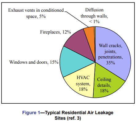
A key issue when addressing air leakage is the significant difference between air leakage at discreet sites, such as at member junctions and at door and window openings where caulking and sealing is at issue, versus the diffuse air leakage that can occur directly through a wall assembly. Chapter 16 of the ASHRAE Fundamentals Handbook (ref. 3) includes the results of residential air leakage studies that show that the largest source of air leakage occurs through wall cracks, joints and utility penetrations. Other major leakage sources include leakage around doors and windows, ceiling penetrations and utility penetrations to the attic, and the HVAC system. The same studies showed that diffusion through walls was less than 1%; i.e., compared to infiltration through holes and other openings, diffusion through walls was not an important flow mechanism in residential buildings. These data are illustrated in Figure 1.
AIR LEAKAGE CRITERIA
To reduce air leakage rates, air barrier systems are sometimes designed and installed as part of the building envelope. Alternatively, the thermal envelope can be designed and detailed to perform as an air barrier system. Current building codes (ref. 4) do not stipulate quantitative requirements for air barriers, but instead require that the exterior envelope be sealed to minimize the infiltration/exfiltration of air through both commercial and residential building envelopes.
The 2012 International Energy Conservation Code (IECC) (ref. 5) and some local jurisdictions, however, have adopted performance requirements for the control of air leakage in commercial buildings. The 2012 IECC provides three levels of compliance, applying to air barrier materials, air barrier assemblies, or the whole building. These commercial air barrier criteria apply only to buildings in Climate Zones 4 through 8. The compliance criteria are (only one of these criteria need to be satisfied):
- a building material intended to serve as an air barrier must have an air permeance of less than 0.004 cfm/ft2 at a pressure differential of 1.57 lb/ft2 (0.02 L/s-m2 at 75 Pa),
- an assembly of materials intended to serve as an air barrier, such as a concrete masonry wall assembly, must have an air leakage rate of less than 0.04 cfm/ft2 at a pressure differential of 1.57 lb/ft2 (0.2 L/s-m2 at 75 Pa), or
- a building must have an air leakage rate of less than 0.4 cfm/ft2 at a pressure differential of 1.57 lb/ft2 (2.0 L/s-m2 at 75 Pa).
Also contained within the code are several “deemed-to-comply” materials and assemblies. The following masonry-related materials and assemblies are included in this list and are therefore considered to comply with the code:
- fully grouted concrete masonry (although listed as a material, this compliance option is more accurately deemed an assembly),
- as a material, portland cement/sand parge or gypsum plaster with a minimum thickness of 5 /8 in. (16 mm),
- as an assembly, portland cement/sand parge, stucco or plaster with a minimum thickness of 1 /2 in. (13 mm), and
- concrete masonry walls coated with one application of block filler and two applications of a paint or sealer coating.
The last option is justified based on research completed in the early 2000s. More recent research has documented additional options for materials and coatings to allow concrete masonry assemblies to comply with the maximum assembly air leakage requirement of 0.04 cfm/ft2 at a pressure differential of 1.57 lb/ft2 (0.2 L/s-m2 at 75 Pa). Although not included explicitly in the code, these tested assemblies can be approved under IECC Section 102, Alternate Materials, as meeting the intent of the code. The testing is described in the Masonry Wall Assemblies section below, and the results are summarized in the Guidelines section on page 7.
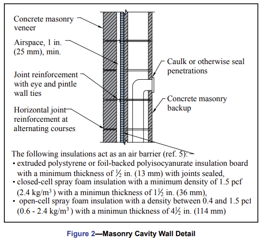
The 2012 IECC also lists the following materials as acceptable air barrier materials (ref. 5). Any one of these can be used in conjunction with concrete masonry construction, as shown in Figures 2 and 3.
- extruded polystyrene insulation board with a minimum thickness of 1/2 in. (13 mm) with joints sealed,
- foil-backed polyisocyanurate insulation board with a minimum thickness of 1/2 in. (13 mm) with joints sealed,
- closed-cell spray foam insulation with a minimum density of 1.5 pcf (2.4 kg/m3) with a minimum thickness of 1 1/2 in. (36 mm),
- open-cell spray foam insulation with a density between 0.4 and 1.5 pcf (0.6 – 2.4 kg/m3) with a minimum thickness of 4 1/2 in. (114 mm), and
- gypsum wallboard with a minimum thickness of 1/2 in. (13 mm) with joints sealed.
MASONRY WALL ASSEMBLIES
Multi-Wythe Walls
Multi-wythe concrete masonry assemblies have a variety of options available for compliance with the commercial building air leakage requirements listed above. In addition to the deemed-to-comply options, there are many proprietary air barrier materials and accessories available. Most air barrier materials are some type of coating, which is usually applied to the cavity side of the back up wythe. In addition, some types of spray-applied insulation or rigid insulation (with sealed joints) can be used as an air barrier, as illustrated in Figure 2.
Single Wythe Walls
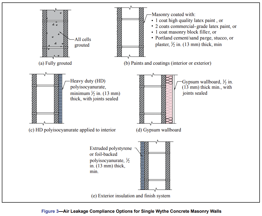
The available options for single-wythe concrete masonry assemblies are illustrated in Figure 3. Solid grouting is available, as well as coating with a paint, sealer, or block filler. Additionally, exterior wallcoverings and interior wall finishes offer solutions, such as parge coating, stucco, plaster, various insulations and gypsum wallboard. Note that paints, sealers or block fillers are effective when applied to either the interior or exterior surface of the concrete masonry. Hence, when a coating is specified, architectural finishes need not be compromised by the coating.
Concrete Masonry Air Leakage Testing
Research sponsored by CMHA and the NCMA Education and Research Foundation (refs. 6, 7) has documented additional concrete masonry wall assemblies that can meet the air barrier assembly requirements of 0.04 cfm/ft2 at a pressure differential of 1.57 lb/ft2 (0.2 L/s-m2 at 75 Pa). The results are summarized below. See References 6 and 7 for full descriptions of the assemblies and test results.
Commercial-Grade Latex Paint
One project (ref. 6) tested the effects of commercial-grade latex paint on the air leakage rate of concrete masonry wall assemblies. The walls were ungrouted except at the four edges (which were grouted solid to isolate air permeance to a 1 m2 test surface). The research employed a modified ASTM E2178, Standard Test Method for Air Permeance of Building Materials (ref. 8), because there is no standardized test procedure specifically suited for testing concrete masonry assemblies. Three wall sets were built using plain gray concrete masonry units, each with different concrete mix designs, then tested for air leakage.
The wall sections were painted with a typical commercial-grade latex paint (28% solids content by volume), then the air leakage rate was re-measured. The research documented that the air leakage rate decreased as the paint thickness increased: it was determined that the air leakage rate of the wall was inversely proportional to the thickness of the paint applied.
While surface texture was not directly measured in this study, it is believed that the surface texture of smooth-faced concrete masonry units affects the ability of the coating material to develop a continuous coating, which is important for reducing air leakage rates through assemblies.
The results of this research indicate that the air leakage rate of 12-in. (305-mm) concrete masonry walls can be reduced to 0.04 cfm/ft2 or less at a pressure differential of 1.57 lb/ft2 (0.20 L/s-m2 at 75 Pa) by applying between 3.3 and 14.6 mils (0.084 and 0.371 mm) of commercial-grade latex paint for concrete masonry units with a smooth textured surface and a coarse textured surface, respectively.
High-Quality Latex Paint
More recent research (ref. 7) evaluated the effects of four additional coatings: a high-quality latex paint, masonry block filler, water repellent surface coatings, and gypsum wallboard. The concrete masonry units used in this study were also plain gray, medium-weight “utility” type units with a fairly open surface texture (see Figure 4). The use of integral water repellent admixtures was also investigated.
The latex paint used in this project was a high quality retail paint, with a 28% solids content by volume and 47% solids content by weight. To evaluate this paint, a single coat was applied with an average dry film thickness of 1.28 mil (0.033 mm). The paint reduced the air leakage rate by 94%, to a calculated average air leakage rate of 0.011 cfm/ft2 (0.05 L/s-m2), well below the assembly requirement of 0.04 cfm/ft2 (0.2 L/s-m2).
The results indicate that when a high quality latex paint is used, a single coat is all that is necessary to create a continuous coating and provide the required barrier to air flow.
Masonry Block Filler
The block filler evaluated was a water-based masonry primer designed for use on concrete and concrete masonry surfaces. This material is typically used as a base primer coat on concrete and masonry surfaces in preparation for painting. It is a thicker coating material than latex paint, designed to fill pores and surface imperfections in masonry walls. Based on information provided by the manufacturer, this material has a 46% solids content by volume and 55% solids content by weight.
A single coat of block filler was applied with an average dry film thickness of 2.10 mil (0.053 mm). The air leakage rate was reduced by 86% due to the presence of the block filler coating, to 0.011 cfm/ft2 (0.05 L/s-m2). This result is well below the air barrier assembly requirement of 0.04 cfm/ft2 (0.2 L/s-m2).
Gypsum Wallboard
A set of assemblies was also evaluated for air leakage after installing ½ in. (12.7 mm) gypsum wallboard to simulate a single-wythe assembly with a drywall-finished interior.
When the gypsum wallboard was tested by itself, it had an air permeance below the air barrier material requirement of 0.004 cfm/ft2 (0.02 L/s-m2). When the concrete masonry assembly was tested with wallboard attached, it was evident that the performance of the assembly was dominated by the air permeance of the wallboard, as very little air leakage was measured, and the results were below the 0.004 cfm/ft2 (0.02 L/s-m2) requirement for an air barrier material.

Water-Repellent Surface Coatings
Because many single-wythe concrete masonry assemblies use some type of water repellent surface coating, these coatings may be an efficient way to reduce air leakage rates. Both a silane/siloxane and an acrylic microemulsion water repellent coating were evaluated.
While both water repellent coatings reduced the air leakage rate of the assemblies, the reduction was not sufficient to comply with the 2012 IECC air barrier assembly requirements for commercial buildings.
Integral Water Repellents
The effect of an integral water repellent in concrete masonry units and masonry mortar was also evaluated. Integral water repellents in concrete masonry units can improve the compaction of the unit, leading to a slightly tighter concrete matrix and, in some cases, a more uniform surface texture.
The tested set of concrete masonry assemblies contained an integral water repellent admixture at an appropriate dosage to produce water repellent characteristics.
Compared to the assemblies without an integral water repellent, the addition of integral water repellent decreased the air leakage rate by 28% on average. This decrease is likely due to a slightly tighter pore structure resulting from the use of the integral water repellent. The decrease in leakage rate, however, was not sufficient to reduce the assembly air leakage rate to levels that comply with the 2012 IECC.
CONCRETE MASONRY COMPARED TO FRAME CONSTRUCTION
Typical masonry construction does not include some of the leakage sites common in frame walls. Masonry walls do not have sole plates (sills), because the wall is a continuous assembly from the footing up. The top of a masonry wall is typically a tie-beam or bond beam. Trusses or rafters are set to a plate attached to the top course of masonry. Quality caulking and sealing are important at the ceiling finish edge. Sealing is also required at attic access ways, as well as around any wall penetrations.
Commercial Buildings
Measured air leakage rates from existing commercial buildings constructed during or after 1980 have been compiled (ref. 9). From this data, 84% of the masonry buildings included had measured whole-building air leakage rates of less than 2 cfm/ft2 at a pressure differential of 1.57 lb/ft2 (10 L/s-m2at 75 Pa). In comparison, only 30% of frame-walled buildings had measured whole building air leakage rates of less than 2 cfm/ft2 at a pressure differential of 1.57 lb/ft2 (10 L/s-m2 at 75 Pa) (it should be noted that none of these buildings were constructed to meet an air tightness standard). The reported leakage rates were normalized by the above grade area of the building envelope. The data were compiled from various references, and represent a range of climates and building types, making it difficult to draw definite conclusions. The results do indicate, however, that existing masonry buildings tend to have much lower air leakage rates than existing frame-walled buildings.
Residential Buildings
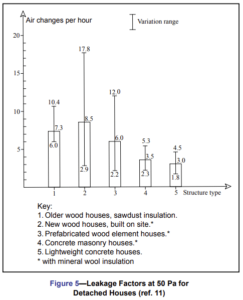
The air leakage rates of masonry walls have also been researched widely in Europe by such groups as the Air Ventilation and Infiltration Center in England (ref. 10). Results from detailed air leakage work performed in Finland show that concrete masonry and lightweight concrete (panelized) walled homes had much lower air leakage rates than wood frame structures (ref. 11). Figure 5 illustrates these differences, comparing older wood frame houses averaging 7.3 air changes per hour (ACH) at 50 Pa to more modern site-built wood frame houses averaging 8.5 ACH, with a very wide range of values. Prefabricated wood element (panelized) houses were better at 6.0 ACH. Both concrete masonry and lightweight concrete houses, however, had roughly one-half the air change rate of the average panelized wood frame homes.
Proper sealing of components into masonry rough openings may be more important than reducing air leakage through masonry assemblies. Dr. Hiroshi Yoshino of Japan’s Tohoku University investigated Japanese housing air leakage (ref. 12) in a broad comparison with data from other nations. He ranked data points from his own research and other investigators into air tightness categories. He observed that some concrete multi-family housing was so air tight that indoor air quality and condensation problems resulted, and ventilation was required. Concrete masonry houses of “air-tight” construction ranked among the best in Japan for air tightness. Several of the other Japanese reports he cited also showed concrete and concrete masonry houses to have lower air leakage rates than typical Japanese frame houses.
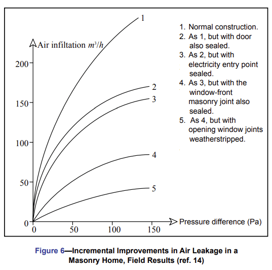
Belgian researchers used a sequential technique in masonry homes to examine incremental air leakage measures (ref. 14). Figure 6 shows the progression of air change rates at 50 Pa from “normal construction,” which evidently assumes no air leakage reduction measures, to a masonry wall with all windows, doors and penetrations sealed and weather stripped. Sealing just these items resulted in about 87% less air leakage. The largest improvements are seen after sealing the door and window frames to their respective rough openings, which agrees with the data in ASHRAE (ref. 3). The Belgian findings also agree with a statement in a compendium of European air leakage results which states: “The critical details from the point of view of air-tightness are associated with the (quality of) formation of openings in masonry walls…” (ref. 14).
IMPACTS ON MOISTURE
When an air barrier material is required, its placement can be critical to controlling moisture and hence to wall durability.
First, because air movement can carry a significant amount of moisture into or through a building assembly, and second because the air barrier can act as a vapor retarder. Note that an air barrier is designed to control the movement of air both into and out of the building envelope, whereas a vapor retarder is designed to restrict the diffusion of water vapor through building materials and subsequent condensation. Because a vapor retarder can also inhibit drying, the need for a vapor retarder varies with climate, construction type and building use.
Although the functions of air barriers and vapor retarders differ, in some cases one component can serve both needs. In designs where one material is installed to control both air and water vapor movement, it is important that the material is continuous to provide the required level of air tightness. Where separate airflow and vapor retarders are installed, care must be taken to ensure that the air barrier cannot cause moisture condensation. This can be accomplished through the choice of vapor-permeable materials or through proper placement.
More detailed information on vapor retarders in concrete masonry walls can be found in TEK 06-17B, Condensation Control in Concrete Masonry Walls (ref. 13).
DISCUSSION
Air leakage measurements indicate that properly constructed concrete masonry walls may have better natural resistance to air leakage than typical frame construction. If a further reduction in air leakage rates is required, various options are available. Retrofits for reducing air leakage in concrete masonry construction are straightforward, because fewer dissimilar joints are involved. Also stucco, paints and mastics tend to be less expensive than new sheathing, polymer papers, etc.
GUIDELINES
The following concrete masonry wall assemblies are considered to meet an air leakage of less than 0.04 cfm/ft2 (0.20 L/s-m2) at 75 Pa,
either by prescriptive code requirements or as demonstrated through laboratory testing.
By prescriptive IECC criteria (ref. 5):
- Fully grouted concrete masonry.
- Concrete masonry with a portland cement/sand parge, stucco or plaster with a minimum thickness of 1/2 in. (13 mm).
- Concrete masonry walls coated with one application of block filler and two applications of a paint or sealer coating.
- By laboratory testing (refs. 6, 8):
- 12-in. (305-mm) concrete masonry sealed with at least two coats of commercial-grade latex paint.
- 8-in. (203-mm) concrete masonry coated with a single coat of high quality latex paint.
- 8-in. (203-mm) concrete masonry coated with a single coat of masonry block filler.
It can be reasonably assumed that compliance would also be achieved by applying these coatings to walls having a larger thickness than those tested.
When coatings such as paint or block filler are called for, they can be applied to either the interior or exterior side of the concrete masonry, so any masonry architectural finishes need not be compromised.
REFERENCES
- Sherman, Max H. and Iain S. Walker, LBNL 62341. Energy Impact of Residential Ventilation Norms in the United States, Lawrence Berkeley National Laboratory, 2007.
- Carr, D. and J. Keyes, Component Leakage Values and their Relationship to Air Infiltration, Steven Winter Associates, 1984.
- 2009 ASHRAE Handbook – Fundamentals. American Society of Heating, Refrigerating and Air-Conditioning Engineers, Inc., 2009.
- International Energy Conservation Code. International Code Council, 2006 and 2009.
- International Energy Conservation Code. International Code Council, 2012.
- Biggs, David T., Air Permeance Testing of Concrete Masonry Wall Assemblies, FR06. National Concrete Masonry Research and Development Laboratory, January 2008.
- Assessment of the Effectiveness of Water Repellents and Other Surface Coatings on Reducing the Air Permeance of Single Wythe Concrete Masonry Assemblies, MR36. Concrete Masonry & Hardscapes Association, 2010.
- Standard Test Method for Air Permeance of Building Materials, E2178-03. ASTM International, 2003.
- Emmerlich S. J., T. McDowell, W. Anis, Investigation of the Impact of Commercial Building Envelope Airtightness on HVAC Energy Use, NISTIR 7238. National Institute of Standards and Technology, 2005.
- Air Ventilation and Infiltration Center, Old Bracknell Lane West, Bracknell, Berkshire, RG12 4AH, Great Britain.
- Kohonen, R., S. Ahvenainen and P. Saarnio. Review of Air Infiltration Research in Finland, Air Infiltration Review Vol. 6, No. 1, 1984.
- Yoshiro, Dr. H. Overview of Air Infiltration in Japan, Air Infiltration Review. Vol. 5 No. 3, May 1984.
- Condensation Control in Concrete Masonry Walls, TEK 06-17B, Concrete Masonry & Hardscapes Association, 2011.
- Caluwaerts, P. and P. Nusgens. Overview of Research Work in Air Infiltration and Related Areas in Belgium, Air Infiltration Review. Vol. 5 No. 1, 1983.