
INTRODUCTION
Masonry connectors can be classified as wall ties, anchors or fasteners. Wall ties connect one masonry wythe to an adjacent wythe. Anchors connect masonry to a structural support or frame. Fasteners connect an appliance to masonry. This TEK covers metal wall ties and anchors. Fasteners are discussed in TEK 12-05 (ref. 1).
The design of anchors and ties is covered by the International Building Code and Building Code Requirements for Masonry Structures (refs. 2, 3).These provisions require that connectors be designed to resist applied loads and that the type, size and location of connectors be shown or indicated on project drawings. This TEK provides a guide to assist the designer in determining anchor and tie capacity in accordance with the applicable standards and building code requirements.
DESIGN CRITERIA
Connectors play a very important role in providing structural integrity and good serviceability. As a result, when selecting connectors for a project, designers should consider a number of design criteria. Connectors should:
- Transmit out-of-plane loads from one wythe of masonry to another or from masonry to its lateral support with a minimum amount of deformation. It is important to reduce the potential for cracking in masonry due to deflection. There is no specific criteria on connector stiffness, but some authorities suggest that a stiffness of 2,000 lb/in. (350 kN/m) is a reasonable target.
- Allow differential in-plane movement between two masonry wythes connected with ties. This is especially significant as more insulation is used between the outer and inner wythes of cavity walls and where wythes of dissimilar materials are anchored together. On the surface, it may appear that this criterion is in conflict with Item 1, but it simply means that connectors must be stiff in one direction (out-of-plane) and flexible in the other (in plane). Note that some connectors allow much more movement than unreinforced masonry can tolerate (see ref. 27 for a discussion of potential masonry wall movements). In order to preserve the in-plane and out-of-plane wall tie stiffness, current codes (refs. 2, 3) allow cavity widths up to 4 1/2 in. (114 mm) without performing wall tie analysis. With an engineered analysis of the wall ties, cavity widths may be significantly increased to accommodate thicker insulation.
- Meet applicable material requirements:
- plate and bent-bar anchors—ASTM A36 (ref. 4)
- sheet-metal anchors and ties—ASTM A1008 (ref. 5)
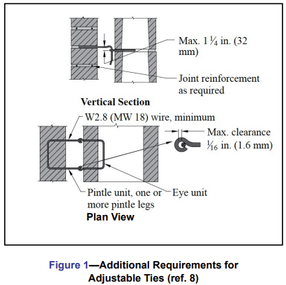
- wire anchors and ties—ASTM A82 (ref. 6), and adjustable wire ties must also meet the requirements illustrated in Figure 1
- wire mesh ties – ASTM A185 (ref. 7)
- Provide adequate corrosion protection. Where carbon steel ties and anchors are specified, corrosion protection must be provided by either galvanizing or epoxy coating in conformance with the following (ref. 8):
A. Galvanized coatings:
- Joint reinforcement in interior walls exposed to a mean relative humidity of 75% or less—ASTM A641 (ref. 13), 0.1 oz zinc/ft2 (0.031 kg zinc/m2)
- Joint reinforcement, wire ties and wire anchors, exterior walls or interior walls exposed to a mean relative humidity greater than 75%—ASTM A153 (ref. 14), 1.5 oz zinc/ft2 (458 g/m2)
- Sheet metal ties or anchors, interior walls exposed to a mean relative humidity of 75% or less—ASTM A653 (ref. 15) Coating Designation G60
- Sheet metal ties or anchors, exterior walls or interior walls exposed to a mean relative humidity greater than 75%—ASTM A153 Class B
- Steel plates and bars, exterior walls or interior walls exposed to a mean relative humidity greater than 75%—ASTM A123 (ref. 16) or ASTM A153 Class B
- Plate and bent-bar anchors—ASTM A480 and ASTM A666 (refs. 10, 11)
- Sheet metal anchors and ties—ASTM A480 and ASTM A240 (refs. 10, 12)
- Wire ties and anchors—ASTM A580
B. Epoxy coatings:
- Joint reinforcement—ASTM A884 (ref. 17) Class A
Type 1 > 7 mils (175 µm) - Wire ties and anchors—ASTM A899 (ref. 18) Class C
20 mils (508 µm) - Sheet metal ties and anchors—20 mils (508 µm) per
surface or per manufacturer’s specification - Where stainless steel anchors and ties are specified,
Specification for Masonry Structures (ref. 8) requires
that AISI Type 304 or 316 stainless steel be provided
that complies with: - Joint reinforcement—ASTM A580 (ref. 9)
- Accommodate construction by being simple in design and easy to install. Connectors should not be so large and cumbersome as to leave insufficient room for mortar in the joints, which can result in a greater tendency to allow water migration into the wall. In the same way, connectors should readily accommodate insulation in wall cavities.
WALL TIE AND ANCHOR REQUIREMENTS
Multiwythe Masonry Wall Types
Wall ties are used in all three types of multiwythe walls (composite, noncomposite and veneer), although some requirements vary slightly depending on the application. The primary differences between these wall systems are in construction details and how the applied loads are assumed to be distributed.
Composite walls are designed so that the masonry wythes act together as a single structural member. This requires the masonry wythes to be connected by masonry headers or by a mortar- or grout filled collar joint and wall ties to help ensure adequate load transfer. TEKs 16-01A and 16-02B (refs. 19, 20) more fully describe composite walls.
In noncomposite masonry (also referred to as a cavity wall), wythes are connected with metal wall ties, but they are designed such that each wythe individually resists the loads imposed on it. Noncomposite walls are discussed in TEKs 16-01A and 16-04A (refs. 19, 21).
In a veneer wall, the backup wythe is designed as the load-resisting system, with the veneer providing the architectural wall finish. Information on veneer walls can be found in TEKs 05-01B and 03 06C (refs. 22, 23). Note that although a cavity wall is defined as a noncomposite masonry wall (ref. 3), the term cavity wall is also commonly used to describe a veneer wall with masonry backup.
Building Code Requirements for Masonry Structures also includes empirical requirements for wire wall ties and strap-type ties used to connect intersecting walls. These requirements are covered in TEK 14-08B (ref. 24).
Wall Ties
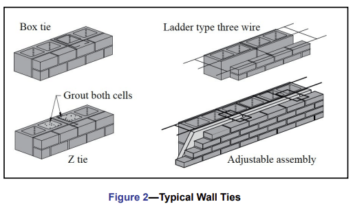
Wire wall ties can be either one piece unit ties, adjustable two piece ties, joint reinforcement or prefabricated assemblies made up of joint reinforcement and adjustable ties (see Figure 2). Note that the 2011 edition of Specification for Masonry Structures allows adjustable pintle ties to have only one leg (previously, two legs were required for this type of wall tie).
Wall ties do not have to be engineered unless the nominal width of the wall cavity is greater than 4 1/2 in. (114 mm). These wall tie analyses are becoming more common as a means to accommodate more thermal insulation in the wall cavity. Masonry cavities up to 14 in. (356 mm) have been engineered. Of note for these analyses is that the span of wire is a more critical factor than cavity width, i.e. the span length of the pintel component typically controls the mode of failure.
The prescribed size and spacing is presumed to provide connections that will be adequate for the loading conditions covered by the code. These wall tie spacing requirements can be found in TEK 03-06C (for veneers) and TEK 16-01A (for composite and noncomposite walls). Note that truss-type joint reinforcement is stiffer in the plane of a wall compared to ladder-type, so it is more restrictive of differential movement. For this reason, laddertype joint reinforcement is recommended when significant differential movement is expected between the two wythes or when vertical reinforcement is used. See TEK 12-02B (ref. 25) for more information.
Additional tests are needed for adjustable anchors of different configurations and for one piece anchors. Proprietary anchors are also available. Manufacturers of proprietary anchors should furnish test data to document comparability with industry-tested anchors.
Anchors are usually designed based on their contributory area. This is the traditional approach, but some computer models suggest that this approach does not always reflect the actual behavior of the anchorage system. However, there is currently no accepted computer program to address this point, so most designers still use the contributory area approach with a factor of safety of three. The use of additional anchors near the edges of wall panels is also recommended and required around large openings and within 12 in. (305 mm) of unsupported edges.
CONSTRUCTION
When typical ties and anchors are properly embedded in mortar or grout, mortar pullout or pushout will not usually be the controlling mode of failure. Specification for Masonry Structures requires that connectors be embedded at least 1 1/2 in. (38 mm) into a mortar bed of solid units. The required embedment of unit ties in hollow masonry is such that the tie must extend completely across the hollow units. Proper embedment can be easily attained with the use of prefabricated assemblies of joint reinforcement and unit ties. Because of the magnitude of loads on anchors, it is recommended that they be embedded in filled cores of hollow units. See TEK 03-06C for more detailed information.
REFERENCES
- Fasteners for Concrete Masonry, TEK 12-05. Concrete Masonry & Hardscapes Association, 2005.
- International Building Code. International Code Council, 2012.
- Building Code Requirements for Masonry Structures, TMS 402-11/ACI 530-11/ASCE 5-11. Reported by the Masonry Standards Joint Committee, 2011.
- Standard Specification for Carbon Structural Steel, A36-ASTM International, 2008.
- Standard Specification for Steel, Sheet, Cold-Rolled, Carbon, Structural, High-Strength Low-Alloy with Improved Formability, A1008-11. ASTM International, 2011.
- Standard Specification for Steel Wire, Plain for Concrete Reinforcement, A82-07. ASTM International, 2007.
- Standard Specification for Steel Welded Wire Reinforcement, Plain, for Concrete, A185-07. ASTM International, 2007.
- Specification for Masonry Structures, TMS 602 -11/ACI 530.1-11/ASCE 6-11. Reported by the Masonry Standards Joint Committee, 2011.
- Standard Specification for Stainless Steel Wire, ASTM A580-08. ASTM International, 2008.
- Standard Specification for General Requirements for Flat Rolled Stainless and Heat-Resisting Steel Plate, Sheet, and Strip, ASTM A480-11a. ASTM International, 2011.
- Standard Specification for Annealed or Cold-Worked Austenitic Stainless Steel, Sheet, Strip, Plate and Flat Bar, ASTM A666-10. ASTM International, 2010.
- Standard Specification for Chromium and Chromium Nickel Stainless Steel Plate, Sheet and Strip for Pressure Vessels and for General Applications, ASTM A240-11a. ASTM International, 2011.
- Standard Specification for Zinc-Coated (Galvanized) Carbon Steel Wire, ASTM A641-09a. ASTM International, 2009.
- Standard Specification for Zinc Coating (Hot-Dip) on Iron and Steel Hardware, ASTM A153-09. ASTM International, 2009.
- Standard Specification for Steel Sheet, Zinc-Coated Galvanized or Zinc-Iron Alloy-Coated Galvannealed by the Hot-Dip Process, ASTM A653-10. ASTM International, 2010.
- Standard Specification for Zinc (Hot-Dip Galvanized) Coating on Iron and Steel Products, ASTM A123-09. ASTM International, 2009.
- Standard Specification for Epoxy-Coated Steel Wire and Welded Wire Fabric for Reinforcement, ASTM A884-06. ASTM International, 2006.
- Standard Specification for Steel Wire Epoxy Coated, ASTM A899-91(2007). ASTM International, 2007.
- Multiwythe Concrete Masonry Walls, TEK 16-01A, Concrete Masonry & Hardscapes Association, 2005.
- Structural Design of Unreinforced Composite Masonry, TEK 16-02B, Concrete Masonry & Hardscapes Association, 2002.
- Design of Concrete Masonry Noncomposite (Cavity) Walls, TEK 16-04A, Concrete Masonry & Hardscapes Association, 2004.
- Concrete Masonry Veneer Details, TEK 05-01B, Concrete Masonry & Hardscapes Association, 2003.
- Concrete Masonry Veneers, TEK 03-06C, Concrete Masonry & Hardscapes Association, 2012.
- Empirical Design of Concrete Masonry Walls, TEK 14-08B, Concrete Masonry & Hardscapes Association, 2008.
- Joint Reinforcement for Concrete Masonry, TEK 12-02B, Concrete Masonry & Hardscapes Association, 2005.
- Porter, Max L., Lehr, Bradley R., Barnes, Bruce A., Attachments for Masonry Structures, Engineering Research Institute, Iowa State University, February 1992.
- Crack Control Strategies for Concrete Masonry Construction, CMU-TEC-009-23, Concrete Masonry & Hardscapes Association, 2023.