
INTRODUCTION
Varying the bond or joint pattern of a concrete masonry wall can create a wide variety of interesting and attractive appearances using standard units as well as sculptured-face and other architectural units. Because concrete masonry is often used as the finished wall surface, the use of bond patterns other than the traditional running bond has steadily increased for both loadbearing and nonloadbearing walls.
Building code allowable design stresses, lateral support, and minimum thickness requirements for concrete masonry are based primarily on structural testing and research on wall panels laid in running bond construction. When a different bond pattern is used it is advisable to consider its influence on the compressive and flexural strength of a block wall. Some building codes provide for variations in bond pattern to some extent by requiring the use of horizontal reinforcement, for example, when walls are laid in stack bond.
STACK BOND CONSTRUCTION
Excluding running bond construction, the most popular and widely used bond pattern with concrete masonry units is stack bond. Compressive strength is similar for stack and running bond construction. In stack bond masonry, heavy concentrated loads will be carried down to the support by the particular vertical tier or “column” of masonry under the load, with little distribution to adjacent masonry. Stability will not be jeopardized if allowable stresses are not exceeded, but the use of reinforced bond beams will aid in distributing concentrated loads. The use of pilasters or grouted cells will also be effective in increasing the resistance to concentrated loads.
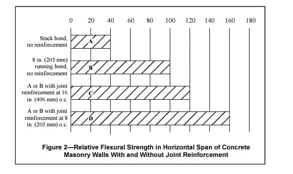
The flexural strength of stack bond walls spanning horizontally can be increased significantly by the use of bond beams or joint reinforcement. The value of joint reinforcement as a means of strengthening concrete masonry in the horizontal span is indicated in Figure 4 which shows the relative flexural strength with and without joint reinforcement. From this it can be seen that properly reinforced stack bond masonry can be designed to be as strong as running bond construction.
CODE REQUIREMENTS
Building Code Requirements for Masonry Structures (ref. 1) includes criteria for walls laid in stack bond. Although stack bond typically refers to masonry constructed such that the head joints are vertically aligned, the Code defines stack bond as masonry laid such that the head joints in successive courses are horizontally offset less than one quarter the unit length, as illustrated in Figure 1.
All stack bond construction is required to have a minimum area of horizontal reinforcement equal to 0.00028 times the gross vertical cross-sectional area of the wall. This requirement can be met using either bond beams spaced not more than 48 in. (1219 mm) on center or using joint reinforcement. Anchored masonry veneer must have horizontal joint reinforcement, of at least one wire size W1.7 (9 gauge) (MW11) or larger, spaced at a maximum of 18 in. (457 mm) on center vertically. This is equivalent to the minimum reinforcement stated above for a nominal 4 in. (102 mm) wythe.
When stack bond construction may be subjected to seismic loads or winds of hurricane velocity, consideration must be given to additional requirements and restrictions as may be consistent with local codes, local experience, and engineering practice. For example, Building Code Requirements for Masonry Structures requires stack bond masonry in Seismic Design Category D and higher to be solidly grouted hollow open-end units, fully grouted hollow units with full head joints, or solid units with a maximum spacing of 24 in. (610 mm) for the reinforcement. Seismic Design Category E & F have an additional requirement that the horizontal reinforcement be at least 0.0015 the gross cross-sectional area of walls that are not part of the lateral-force resisting system. For walls that are part of the lateral force resisting system in SDC E & F, the minimum horizontal reinforcement requirement is increased to 0.0025 times the gross cross-sectional area with a maximum spacing of 16 in. (406 mm). These elements also must be solidly grouted hollow open end units or two wythes of solid units.

TESTING PROGRAM
To assist in evaluating the structural performance of walls laid with various bond patterns, a large number of concrete masonry panels were tested for compressive and flexural strength (ref. 2). The nine bond patterns shown in Figure 2 were employed in constructing the test panels. Panels were composed of 8 in. (203 mm) hollow units laid up with Types M and S mortar with face shell bedding. Panels were 4 ft wide by 8 ft high (1.2 by 2.4 m); those for flexural strength tests with the wall spanning horizontally between supports were 8 ft wide by 4 ft high (2.4 by 1.2 m). For compressive strength tests, loading was applied at an eccentricity of one-sixth of the wall thickness. Lateral tests used uniformly distributed loading from a plastic bag filled with air. Test methods and details followed those specified in Standard Methods of Conducting Strength Tests of Panels for Building Construction, ASTM E 72 (ref. 3)
Relative strengths of the wall panels are compared by bond pattern in Figure 3 using 8 in. (203 mm) high units laid in running bond as the standard.

Compressive Strengths
From Figure 3 it is evident that where hollow units are laid in the horizontal position there is no decrease in wall compressive strength for the different bonding patterns. Units laid in the vertical or diagonal position generally produce wall strengths approximately 75% of that obtained from the running bond pattern. The reduction in strength for vertical stack bond is directly related to the decrease in net block area in compression. In the vertical position, the end webs and interior webs are so oriented with respect to the direction of stress that they do not contribute to the strength of the wall except as ties between the face shells. When blocks are laid in the horizontal position, the end and middle webs are parallel to the direction of stress and contribute to the strength of the wall.

Vertical Span Flexural Strength
Where walls span vertically between lateral supports, failure from transverse loading occurs as a bond failure between block and mortar. Only three of the bond patterns tested showed a decrease in flexural strength when compared to the standard: vertical stack, basket weave “B”, and coursed ashlar. In two of these patterns the continuous horizontal joints are farther apart than the standard running bond pattern. Horizontal stack bond construction was 30% stronger in vertical span flexure, and walls built with units laid in a diagonal position were more than 50% stronger because more mortar bond area is included in the “saw-tooth” line across the wall width.
Horizontal Span Flexural Strength
For unreinforced concrete masonry laid in running bond and spanning horizontally between lateral supports, flexural resistance depends on the strength and design of the block. Under increasing lateral load the units will rupture in tension rather than failing by mortar bond. For this reason, walls are generally at least twice as strong in flexure when spanning horizontally. This does not apply to walls laid in stack bond, which have approximately the same strength in both directions. Test results shown in Figure 4 indicate that the relative strength of stack bond walls in the horizontal span is about 30% of running bond construction.
REFERENCES
- Building Code Requirements for Masonry Structures, ACI 530-02/ASCE 5-02/TMS 402-02. Reported by the Masonry Standards Joint Committee, 1999.
- Load Tests of Patterned Concrete Masonry Walls. Portland Cement Association, 1961.
- Standard Methods of Conducting Strength Tests of Panels for Building Construction, ASTM E 72. ASTM International.