INTRODUCTION
The combination of concrete masonry and steel reinforcement provides a strong structural system capable of resisting large compressive and flexural loads. Reinforced masonry structures have significantly higher flexural strength and ductility than similarly configured unreinforced structures and provide greater reliability in terms of expected load carrying capacity at failure.
Concrete masonry elements can be designed using several methods in accordance with the International Building Code (IBC, ref. 1) and, by reference, Building Code Requirements for Masonry Structures (MSJC Code, ref. 2): allowable stress design, strength design, direct design, empirical design, or prestressed masonry. The design tables in this TEK are based on allowable stress design provisions.
The content presented in this edition of TEK 14-19B is based on the requirements of the 2012 IBC (ref. 1a), which in turn references the 2011 edition of the MSJC Code (ref. 2a). For designs based on the 2006 or 2009 IBC (refs. 1b, 1c), which reference the 2005 and 2008 MSJC (refs. 2b, 3c), respectively, the reader is referred to TEK 14-19B (ref. 3).
Significant changes were made to the allowable stress design (ASD) method between the 2009 and 2012 editions of the IBC. These are described in detail in TEK 14-07C, ASD of Concrete Masonry (2012 IBC & 2011 MSJC) (ref. 4), along with a detailed presentation of all of the allowable stress design provisions of the 2012 IBC.
LOAD TABLES
Tables 1 and 2 list the maximum bending moments and shears, respectively, imposed on walls simply supported at the top and bottom and subjected to uniform lateral loads with no applied axial loads.

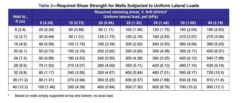
A Based on walls simply supported at top and bottom, no axial load.
WALL CAPACITY TABLES
Tables 3, 4, 5 and 6 contain the maximum bending moments and shear loads that can be sustained by 8-, 10-, 12-, and 16-in. (203-, 254-, 305-, 406 mm) walls, respectively, without exceeding the allowable stresses defined in the 2012 IBC and 2011 MSJC (refs. 1a, 2a). These wall strengths can be compared to the loads in Tables 1 and 2 to ensure the wall under consideration has sufficient design capacity to resist the applied load.
The values in Tables 3 through 6 are based on the following criteria:
- Maximum allowable stresses:

- f’m = 1500 psi (10.3 MPa)
- Em = 900f’m or 1,350,000 psi (9,310 MPa)
- Es = 29,000,000 psi (200,000 MPa)
- Type M or S mortar
- running bond or bond beams at 48 in. (1,219 mm) max o.c.
- reinforcement spacing does not exceed the wall height
- only cores containing reinforcement are grouted.
Reinforcing Steel Location
Two sets of tables are presented for each wall thickness. Tables 3a, 4a, 5a and 6a list resisting moment and resisting shear values for walls with the reinforcing steel located in the center of the wall. Centered reinforcing bars are effective for providing tensile resistance for walls which may be loaded from either side, such as an above grade exterior wall which is likely to experience both wind pressure and suction.
Tables 3b, 4b, 5b and 6b list resisting moment and resisting shear values for walls with the reinforcing steel offset from the center.
Placing the reinforcement farther from the compression face of the masonry provides a larger effective depth of reinforcement, d, and correspondingly larger capacities. A single layer of off-center reinforcement can be used in situations where the wall is loaded from one side only, such as a basement wall with the reinforcement located towards the interior. For walls where loads can be in both directions (i.e. pressure or suction), two layers of reinforcement are used: one towards the wall exterior and one towards the interior to provide increased capacity under both loading conditions. In Tables 3b, 4b, 5b and 6b, the effective depth of reinforcement, d, is a practical value which takes into account construction tolerances and the reinforcing bar diameter.
Figure 1 illustrates the two steel location cases.


DESIGN EXAMPLE
A warehouse wall will span 34 ft (10.4 m) between the floor slab and roof diaphragm. The walls will be constructed using 12 in. (305 mm) concrete masonry units. What is the required reinforcing steel size and spacing to support a wind load of 20 psf (0.96 kPa)?
From interpolation of Tables 1 and 2, respectively, the wall must be able to resist:
M = 34,800 lb-in./ft (12.9 kN-m/m)
V = 340 lb/ft (4.96 kN/m)
Assuming the use of offset reinforcement, from Table 5b, No. 6 bars at 40 in. on center (M#19 at 1,016 mm) or No. 7 bars at 48 in. (M#22 at 1,219 mm) on center provides sufficient strength: for No. 6 bars at 40 in. o.c. (M#19 at 1,016 mm):
Mr = 35,686 lb-in./ft (13.3 kN-m/m) > M OK
Vr = 2,299 lb/ft (33.5 kN/m) > V OK
for No. 7 bars at 48 in. (M#22 at 1,219 mm) :
Mr = 40,192 lb-in./ft (14.9 kN-m/m) > M OK
Vr = 2,133 lb/ft (31.1 kN/m) > V OK
As discussed above, since wind loads can act in either direction, two bars must be provided in each cell when using off-center reinforcement—one close to each faceshell.
Alternatively, No. 6 bars at 24 in (M#19 at 610 mm) or No. 8 at 40 in (M#25 at 1,016 mm) could have been used in the center of the wall.
NOTATION
As = area of nonprestressed longitudinal reinforcement, in.² (mm²)
b = effective compressive width per bar, in. (mm)
d = distance from extreme compression fiber to centroid of tension reinforcement, in. (mm)
Em = modulus of elasticity of masonry in compression, psi (MPa)
Es = modulus of elasticity of steel, psi (MPa)
Fb = allowable compressive stress available to resist flexure only, psi (MPa)
Fs = allowable tensile or compressive stress in reinforcement, psi (MPa)
Fv = allowable shear stress, psi (MPa)
f’m = specified compressive strength of masonry, psi (MPa)
M = maximum calculated bending moment at section under consideration, in.-lb, (N-mm)
Mr = flexural strength (resisting moment), in.-lb (N-mm)
V = shear force, lb (N)
Vr = shear capacity (resisting shear) of masonry, lb (N)
REFERENCES
- International Building Code. International Code Council.
- 2012 Edition
- 2009 Edition
- 2006 Edition
- Building Code Requirements for Masonry Structures. Reported by the Masonry Standards Joint Committee.
- 2011 Edition: TMS 402-11/ACI 530-11/ASCE 5-11
- 2008 Edition: TMS 402-08 /ACI 530-08/ASCE 5-08
- 2005 Edition: ACI 530-05/ASCE 5-05/TMS 402-05
- Allowable Stress Design Tables for Reinforced Concrete Masonry Walls, TEK 14-19B. Concrete Masonry & Hardscapes Association, 2009.
- Allowable Stress Design of Concrete Masonry Based on the 2012 IBC & 2011 MSJC, TEK 14-07C. Concrete Masonry & Hardscapes Association, 2011.