STRUCTURAL TESTING OF CONCRETE MASONRY ASSEMBLAGES
INTRODUCTION
A considerable amount of research has been conducted on concrete masonry units and assemblages in order to develop design stresses for building codes and to evaluate existing building systems. The properties of concrete masonry which are considered most important and which have been the subject of research on assemblages of concrete masonry units include: structural, fi re resistance, thermal insulation, noise insulation, and resistance to moisture penetration. This TEK is concerned with testing structural properties and reviews the kinds of loads and stresses which concrete masonry walls may be subjected to in service and the principal details of ASTM Test Methods used to investigate the structural behavior of masonry walls.
TYPES OF LOADS
Loads acting on masonry walls may be classified as vertical dead and live loads, sometimes called gravity loads, and lateral loads, these being due to wind, earthquake, earth or water pressure, etc. Vertical loads may be more or less uniformly distributed along the length of the wall or may include one or several concentrated loads which are transmitted to small areas of the wall section. Vertical loads may be centered in the same plane as the centroidal axis of the wall (concentric or axial loading) or at some distance away from this axis (eccentric loading). Eccentric loads produce bending as well as direct compressive stresses and consequently are more severe than concentric loading. Lateral loads may be uniformly distributed on the vertical surface as in the case of wind, or nonuniform according to some function of other factors, as in the case of earthquake or fluid pressure loads. Lateral loads may be concentrated and their direction may be normal or parallel to or at any intermediate angle with the wall surface. Loads may be gradually or quickly applied (impact), permanent (dead loads) or transient (wind load). Vertical and lateral loads may act simultaneously to produce a combination of axial compression and flexural stress in the masonry.
TYPES OF LOADING USED IN TESTS
Despite the variety of load types and stress conditions, masonry walls can be safety designed provided their ultimate strength in direct compression, flexure and shear is known. In developing this information the test procedures employed in the past often have varied as to specimen size, loading method and other details, but when properly presented and interpreted the results have proved to be applicable and useful. Beginning in the 1930’s, the National Bureau of Standards adopted standard methods for use in their own investigations of building constructions, these methods later forming the basis for ASTM Standard E 72, Standard Test Method for Conducting Strength Tests of Panels for Building Construction (ref. 2).
Figures 1 through 6 show schematically the general procedures used in conducting compression, flexural, and racking.
COMPRESSION
Test Methods
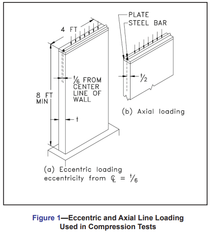
According to ASTM E 72, compressive strength tests are made on specimens having a height equal to the height of the wall in actual use and having a nominal width of 4 ft (1.2 m). Generally, story height walls (nominal height = 8 ft) are typical of those tested but compressive strength tests have been conducted on masonry walls over 20 ft high.
Referring to Figure 1, note that compression tests are made with the load line located a distance one-third the wall thickness from the inside face of the wall (eccentric loading) or at the central plane of the wall (axial loading). Eccentric loading is prescribed in ASTM E 72 and for many years has been preferred over axial loading by many investigators since it approximates more closely the loading condition of walls in buildings.
Loading at the central plane or centerline of the wall is true axial loading only when the wall section is geometrically and elastically symmetrical with respect to the center line.
With the advent of engineered loadbearing masonry design, simpler and less expensive test methods for determining compressive strength properties of masonry have come into wide usage: ASTM E 447, Standard Test Method for Compressive Strength of Masonry Prisms (ref. 1), and ASTM C 1314, Standard Test Method for Constructing and Testing Masonry Prisms Used to Determine Compliance with Specified Compressive Strength of Masonry (ref. 3). These tests prescribe methods for testing short compression prisms made of the same masonry units, mortar, and workmanship to be used in the construction. Although the test methods are similar, ASTM E 447 is intended for research purposes only (not for construction quality assurance purposes as is C 1314), and requires collection of additional detailed information associated with research tests.
Stresses Due to Applied Loads
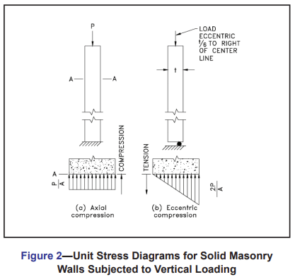
The type of loading largely determines the general shape of the stress distribution diagram for the wall section. For solid walls, Figure 2, axial loading results in rectangular stress diagram, the fiber stresses being uniform over the entire cross section and equal to P/A. If the vertical load is applied eccentrically or off-center by a distance of one-sixth the wall thickness (t/6), the unit stress varies from a maximum of 2P/A at the wall face nearest the load line, to zero stress at the opposite face, Figure 2b. Eccentricity greater than t/6 would produce tensile stresses at the opposite face and a stress diagram which would show zero stress at some point between the wall faces. Eccentricity less than t/6 would result in some compression at the opposite face and a stress diagram of trapezoid shape.
In Figures 2a and 2b, the average compressive stress is the same in each case, assuming the same vertical load, but as noted, the maximum fiber stress for the eccentrically loaded wall is twice that for the axially loaded wall. A logical deduction is that a given wall will support a greater axial than eccentric load. This is borne out by tests which indicate that bending stress due to eccentric location of vertical load or other causes, reduces the ultimate vertical load capacity of masonry below its axial load strength.
FLEXURAL
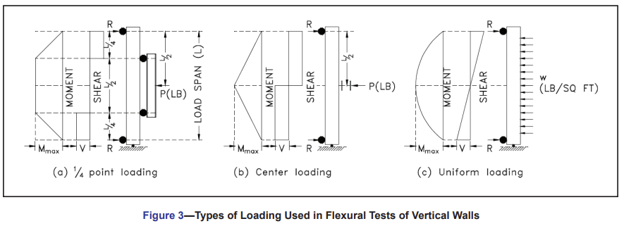
The different types of loading used in testing masonry walls for flexural or transverse strength are shown in Figure 3, together with the moment and shear diagrams and formulas for calculating maximum shear, moment and deflection assuming simply supported spans. ASTM E 72 specifies a specimen width of 4 ft and either line loading applied at the outer 1/4 points of the span as shown in sketch (b) of the figure, or uniformly distributed loading shown in sketch (c). Uniform transverse loading of upright specimens such as masonry walls has become practical and more commonly used with the development of the “bag method” in which a plastic or rubberized fabric bag, interposed between the wall face and a backboard, is inflated with air to give increments of pressure against the wall until failure. Comparing the deflection formulas for the three loading methods, it will be noted that 1/4-point loading causes the greatest deflection, assuming a given moment and wall section, and from this standpoint is more severe than the other two methods. Also, any line load method produces combinations of maximum shear and moment in the same region which generally results in a lower indicated strength than would be obtained with uniform loading where the regions of maximum moment and of maximum shear are widely separated. It also appears that a test loading which does not include concentrated loads more nearly simulates the more common loads considered in design, such as wind and fluid or earth pressure.
Flexural strength of unreinforced masonry assemblages can also be measured by other ASTM methods. Method E 518, Standard Test Method for Flexural Bond Strength of Masonry (ref. 5), is intended to provide simplified and economical means for gathering comparative research data on the flexural bond strength developed with different types of masonry units and mortar or for the purpose of checking job quality control as regards materials and workmanship. Unlike ASTM E 72, Method E 518 is typically not intended for use in establishing design stresses. Specimens are small prisms laid up in stack bond and tested in a horizontal position by applying load at the third-points or by applying a uniform load by means of an inflated air bag.
Method C 1072, Standard Test Method for Measurement of Masonry Flexural Bond Strength (ref. 6) covers physical testing of each joint of masonry prisms using a bond wrench test apparatus. This method permits the measurement of multiple joints in a prism rather than the single joint tests of E 82 and E 518, making statistical evaluations easier and more cost effective. The results are used to: determine compatibility of mortars and masonry units; determine the effect on flexural bond strength of factors such as mortar properties and workmanship; and predict the flexural strength of a wall. The flexural bond strength determined using C 1072 is not typically used to predict the flexural bond strength of a wall constructed of the same material unless testing is performed to document the difference between the two; nor to determine extent of bond for a water permeance evaluation.
RACKING
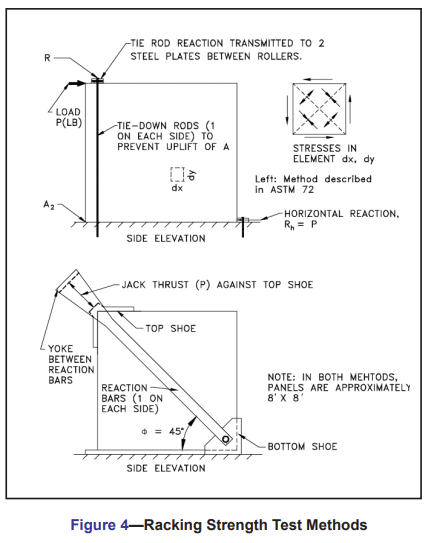
Racking strength tests are performed according to the general schemes shown in Figure 4 and give an indication of the resistance of the construction to the horizontal component of shearing forces acting parallel to the wall. In the method prescribed in ASTM E 72, shown in the upper sketch, the horizontal component is equal to the load P, and the principal stress, compression acting in a diagonal line between the load point and lower right reaction, is the resultant of load P and vertical reaction Rv.
In the scheme shown in the lower sketch, the load is applied diagonally downward and the horizontal component or longitudinal shear is equal to P cosφ , approximately 0.7P since φ is usually about 45o. This alternative method is not addressed in ASTM E 72, but has often been used because it eliminates the need for tie-down rods.
Results of racking tests of masonry walls generally are given in terms of the maximum horizontal component, pounds per linear foot of wall, although the total load P may also be reported. While failure is considered to be in shear, it actually is caused by a combination of shear and secondary tensile stresses, the latter acting normal to the compressive stress. Although exceeding both the shearing and secondary tensile stresses in intensity, compressive stress is not sufficient to cause a compression-type failure.
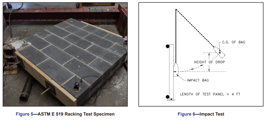
As with compression and flexural testing, an ASTM method exists for testing shear on specimens smaller than required in ASTM E 72. In ASTM E 519, Standard Test Method for Diagonal Tension (Shear in Masonry Assemblages) (ref. 4), 4 ft by 4 ft masonry assemblages are positioned in a compression testing machine so that a compressive load is applied along one diagonal, causing a diagonal tension failure with the specimen splitting apart normal to the direction of load (see Figure 5). This method also avoids the need for a hold down force to prevent rotation of the specimen as used in the E 72 method, simplifying the analysis of the state of stress in the specimen.
IMPACT
The impact test of ASTM E 695 (ref. 7) affords a qualitative measure of the capacity of wall, floor and roof panels to resist impact loading. The impact force is obtained from the free-fall of a bag of lead shot through a path which causes it to strike the center of the panel at an angle normal to the surface. The essential details of the method as adapted to the testing of upright masonry wall panels are shown in Figure 6. Panels are typically 4 ft long and are simply supported on a span six inches less than the height of the specimen. The height of drop is increased in increments until failure occurs, but not exceeding 10 ft, and the maximum drop is the value reported.
The structural testing of masonry walls and assemblages encompasses much more than merely determining the ultimate load at failure. At each load increment, strains and deflections are carefully measured with precision instruments. at various locations on the specimen. In some procedures a load increment is applied and measurements are taken after which the load is released and measurements again taken to determine the residual strain or deflection. The specimen is examined and notes made of any cracking, crushing or other visible distress. This process is repeated at each increase in load so that when the test has been concluded the research engineer has accumulated the data needed to give a clear picture of the structural behavior of the specimen through all stages of loading.
REFERENCES
- Standard Test Method for Compressive Strength for Laboratory Constructed Masonry Prisms, ASTM E 447-97. American Society for Testing and Materials, 1997.
- Standard Test Method for Conducting Strength Tests of Panels for Building Construction, ASTM E 72-95. American Society for Testing and Materials, 1995.
- Standard Test Method for Constructing and Testing Masonry Prisms Used to Determine Compliance with Specified Compressive Strength of Masonry, ASTM C 1314-97. American Society for Testing and Materials, 1997.
- Standard Test Method for Diagonal Tension (Shear) in Masonry Assemblages, ASTM E 519-81(1993)e1. American Society for Testing and Materials, 1993.
- Standard Test Method for Flexural Bond Strength of Masonry, ASTM E 518 -80(1993)e1. American Society for Testing and Materials, 1993.
- Standard Test Method for Measurement of Masonry Flexural Bond Strength, ASTM C 1072-94. American Society for Testing and Materials, 1994.
- Standard Test Method for Measuring Relative Resistance of Wall, Floor, and Roof Construction to Impact Loading, ASTM E 695-79(1997)e1. American Society for Testing and Materials, 1997.