INTRODUCTION
The current trend of urban renewal and infill has sparked a high volume of new low-rise masonry residences. These structures come in many forms, but quite often they employ the use of load-bearing concrete masonry walls supporting a wood floor system. These new buildings are largely derivative of the historic load bearing masonry “brownstone” or “three flat” structures of old. This guide is intended to assist contractors and architects to give this building type a modern approach to detailing.
FLOOR SYSTEM CONNECTIONS
When designing low-rise loadbearing structures, the connection detail between the floor system and the wall system is critical for achieving a watertight structure. Much of this TEK will deal with which strategy should be utilized in connecting a wood floor system to a masonry load-bearing wall. Connection methods covered are joist hangers, beam pockets and ledger beam details. Other floor systems are used in low-rise construction that are not addressed here – see 05-07A for further information (ref. 2).
BRICK AND BLOCK COMPOSITE WALL DETAILS
Quite often, the front facade of these structures is composed of brick to give the building a more residential, more human scale. One way to construct a brick and block wall is to separate the two wythes with an airspace, creating a cavity wall. Another is to use a composite wall design. The composite wall consists of an exterior wythe of brick directly mortared or grouted and tied to an inner wythe of CMU. The collar joint between the two wythes should be 100% solid as it is the only defense against water penetration. Minimum tie requirements are one tie per 22/3ft2 of wall area for W1.7 (MW11)(9 gauge) wire or one tie per 41/2ft2 of wall area using W2.8 (MW19)(3/16 in.)wire (ref. 2). A W1.7 (MW11)(9 gauge) joint reinforcement @16 in. (406 mm) on center would meet this requirement and is often used. Details covered for this system are base flashing, window head and window sill details.
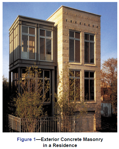
EXTERIOR CONCRETE MASONRY
The use of water repellent admixtures in concrete masonry and mortars can greatly reduce the amount of water entering the masonry. In addition, they inhibit any water that penetrates the face from wicking to the back of the wall.
Proper selection and application of integral water repellents and surface treatments can greatly enhance the water resistive properties of masonry, but they should not be considered as substitutes for good fundamental design including flashing details and crack control measures. See TEKs 19-01, 19-02A, and 19-04A (refs. 6, 3, & 5) for more information on water resistant concrete masonry construction.
Because a 4 in. (102 mm) concrete masonry veneer will shrink over time, a 4 in. (102 mm) hot-dipped galvanized ladder type joint reinforcement should be placed in bed joints spaced 16 in. (406 mm) vertically.
Compared to type N or O, type S mortar tends to be less workable in the field and should only be specified when dictated by structural requirements. Sills, copings and chimney caps of solid masonry units, reinforced concrete, stone, or corrosion resistant metal should be used. Copings, sills and chimney caps should project beyond the face of the wall at least 1 in. (25 mm) and should have functional flashing and weep holes.
In addition, all sills, copings and chimney caps should have a minimum slope of 1:4, be mechanically anchored to the wall, and should have properly sized, sealed, and located movement joints when necessary.
Flashing should be installed at locations shown on the plans and in strict accordance with the details and industry standard flashing procedures. Functional, unpunctured flashing and weep holes are to be used at the base of wall above grade, above openings, at shelf angles, lintels, wall-roofing intersections, chimneys, bay windows, and below sills and copings. The flashing should be extended past the face of the wall. The flashing should have end dams at discontinuous ends, and properly sealed splices at laps.
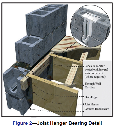
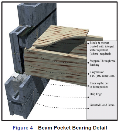
JOIST HANGER DETAILS
The use of a joist hanger system can greatly simplify the bearing detail. The floor system does not interrupt the continuity of the bearing wall. Installation is quicker and easier resulting in a more economical installation.
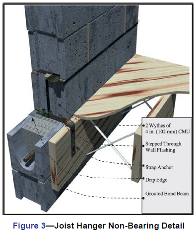
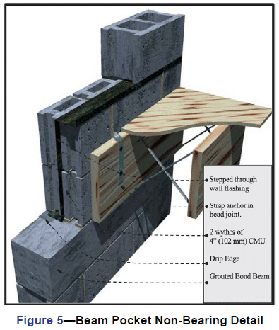
BEAM POCKET DETAILS
The traditional beam pocket detail still can be effective. Stepped flashing above the bearing line is critical to the performance of this system. Without the flashing, any water present in the wall has an unobstructed path inside the building and has the potential to deteriorate the floor structure.
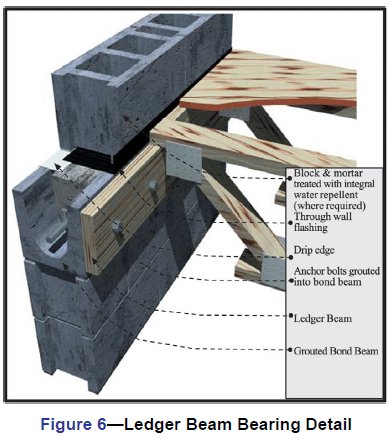
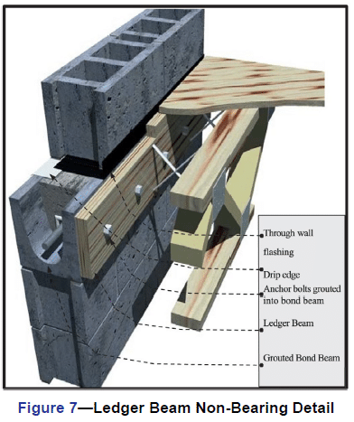
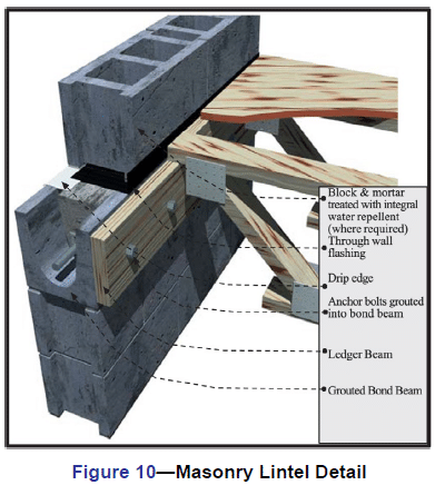
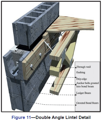
LEDGER BEAM DETAILS
The use of a ledger beam which is bolted to a bond beam is also a good option for this bearing condition. Through wall flashing is still required to maintain a watertight wall. Any water that penetrates the block with run down the inner cores of the block until it hits the flashing. The flashing and weep holes will allow the water to exit without damaging the structure.
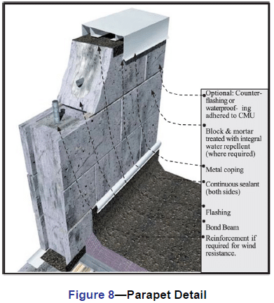
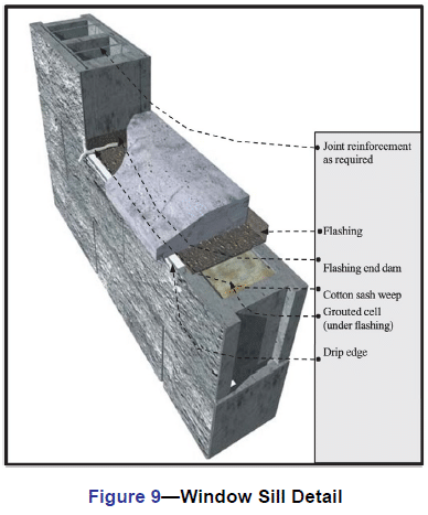
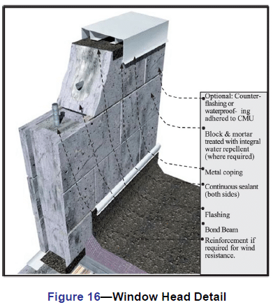
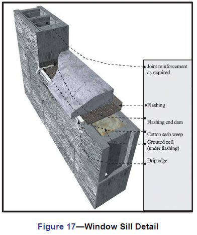
PARAPETS AND WINDOW SILLS
Below are details for a parapet condition and a window sill condition. The parapet is reinforced with No. 4 bars at 48 in. (No.13M @1219 mm) on center or as required for wind resistance. If a metal cap is used, it should extend down the face of the wall at least 3 in. (76 mm) with continuous sealant at the joint on both sides of the wall. The sill detail shows the arrangement of flashing, end dam, weep holes and drip edge and how they all form a watertight
WINDOW HEAD DETAILS
These two window head details show the relationship between the steel lintel, drip edge, flashing, end dams, and weep holes. The first option shows the use of a concrete masonry lintel which is grouted solid and reinforced. The second detail shows two steel lintels used for spanning the opening.
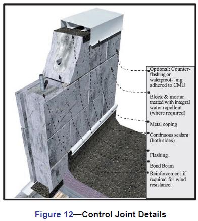
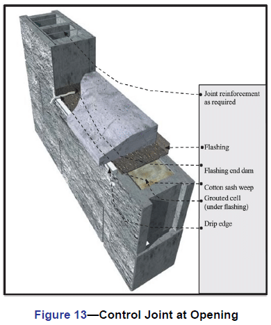
CONTROL JOINT DETAILS
Control joints simply are weakened planes placed at approximately 20 ft. (6 m) on center in concrete masonry walls and at changes in wall elevation/thickness. Notice that the joint reinforcement is discontinuous at the joint. Cores are shown grouted adjacent to the joints as well to ensure structural stability in taller walls and/or high load situations.
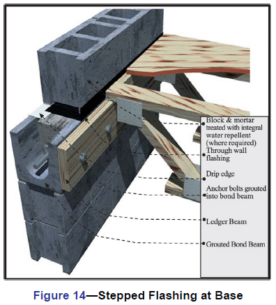
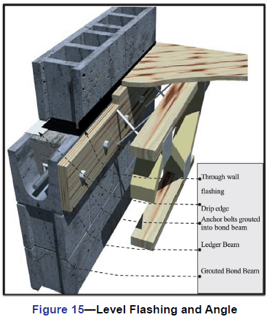
COMPOSITE WALL BASE FLASHING DETAILS
Figure 14 shows a stair-stepped flashing detail with the exposed drip edge and weep holes. Figure 15 shows a straight through wall flashing detail. The flashing must be set in mastic on top of the concrete foundation, or the flashing must be self adhesive. The flashing should be turned up on the inner side of the wall to direct water to the outside of the wall.
COMPOSITE WALL WINDOW DETAILS
Here steel lintels back-to-back create the above window span. Stepped flashing turned up on the inside, and folded to form an end dam protects the head condition from moisture. The sill detail also uses flashing, end dams and weep holes to keep moisture out of the wall. The use of a precast concrete or stone sill is highly suggested over using brick rowlock sills.
CONCRETE MASONRY VENEER DETAILING
Figure 18 shows the detailing of a 4 in. (102 mm) concrete masonry veneer used in conjunction with a 8 in. (205 mm) CMU backup wall.
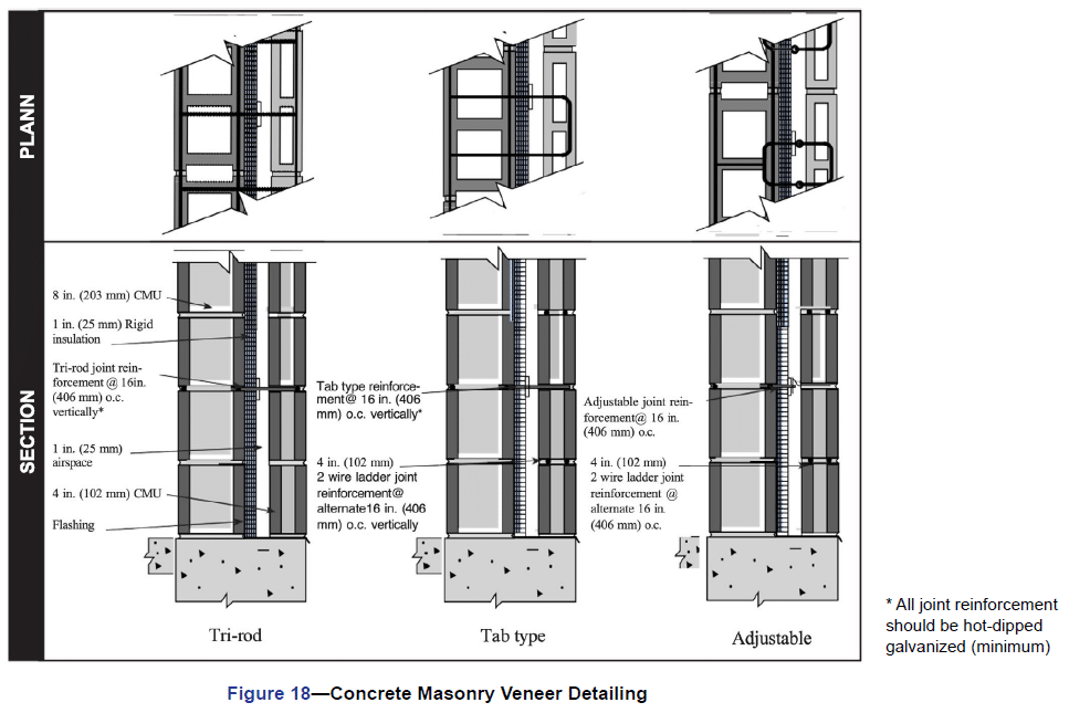
Three types of joint reinforcement are shown including tri-rod, tab and adjustable types. It is imperative that the veneer have a continuous wire embedded in every other course to control movement. With the tri-rod system, the joint reinforcement satisfies this requirement. With the other two systems, an additional ladder type joint reinforcement is used to provide this movement control for the veneer.
REFERENCES
- Building Code Requirements for Masonry Structures,
ACI 530-05/ASCE 6-05/TMS-402-05. Reported by the
Masonry Standards Joint Committee, 2005. - Floor and Roof Connections to Concrete Masonry
Walls, TEK 05-07A, Concrete Masonry & Hardscapes
Association, 2001. - Design for Dry Single-Wythe Concrete Masonry
Walls, TEK 19-02B, Concrete Masonry & Hardscapes
Association, 2004. - Flashing Details for Concrete Masonry Walls, TEK 19-05A,
Concrete Masonry & Hardscapes Association, 2004. - Flashing Strategies for Concrete Masonry Walls, TEK 19-
04A, Concrete Masonry & Hardscapes Association, 2003. - Water Repellents for Concrete Masonry Walls, TEK 19-01,
Concrete Masonry & Hardscapes Association, 2002.