INTRODUCTION
A wall constructed with two or more wythes of masonry can technically be classified in one of three ways, depending on how each individual wythe is designed and detailed. These three wall systems are composite, noncomposite or veneer walls. A true veneer is nonstructural—any contribution of the veneer to the wall’s out-of plane load resistance is neglected.
Building Code Requirements for Masonry Structures (ref. 1) defines veneer as a masonry wythe which provides the exterior finish of a wall system and transfers out-of-plane loads directly to the backing, but is not considered to add load resisting capacity to the wall system.
Noncomposite walls, on the other hand, are designed such that each wythe individually resists the loads imposed on it. Bending moments (flexure) due to wind or gravity loads are distributed to each wythe in proportion to its relative stiffness.
Composite walls are designed so that the wythes act together as a single member to resist structural loads. This requires that the two masonry wythes be connected by masonry headers or by a mortar or grout filled collar joint and wall ties to help ensure adequate load transfer between the two wythes.
The primary function of anchored veneers is to provide an architectural facade and to prevent water penetration into the building. As such, the structural properties of veneers are neglected in veneer design. The veneer is assumed to transfer out-of-plane loads through the anchors to the backup system. Building Code Requirements for Masonry Structures Chapter 6 (ref. 1) includes requirements for design and detailing anchored masonry veneer.
A masonry veneer with masonry backup and an air space between the masonry wythes is commonly referred to as a cavity wall. The continuous air space, or cavity, provides the wall with excellent resistance to moisture penetration and wind driven rain as well as a convenient location for insulation. This TEK addresses concrete masonry veneer with concrete masonry backup.
DESIGN CONSIDERATIONS
Masonry veneers are typically composed of architectural units such as: concrete or clay facing brick; split, fluted, glazed, ground face or scored block; or stone veneer. Most commonly, anchored masonry veneers have a nominal thickness of 4 in. (102 mm), although 3 in. (76 mm) veneer units may be available as well.
Although structural requirements for veneers are minimal, the following design considerations should be accounted for: crack control in the veneer, including deflection of the backup and any horizontal supports; adequate anchor strength to transfer applied loads; differential movement between the veneer and backup; and water penetration resistance.
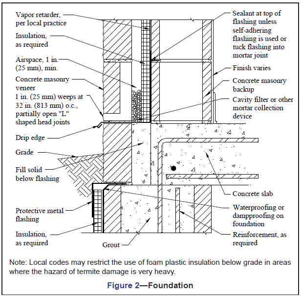
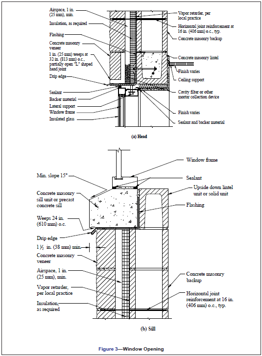
The continuous airspace behind the veneer, along with flashing and weeps, must be detailed to collect any moisture that may penetrate the veneer and direct it to the outside. A minimum 1 in. (25 mm) air space between wythes is required (ref. 1), and is considered appropriate if special precautions are taken to keep the air space clean (such as by beveling the mortar bed away from the cavity or by placing a board in the cavity to catch and remove mortar droppings and fins while they are still plastic). Otherwise, a 2 in. (51 mm) air space is preferred. As an alternative, proprietary insulating drainage products can be used.
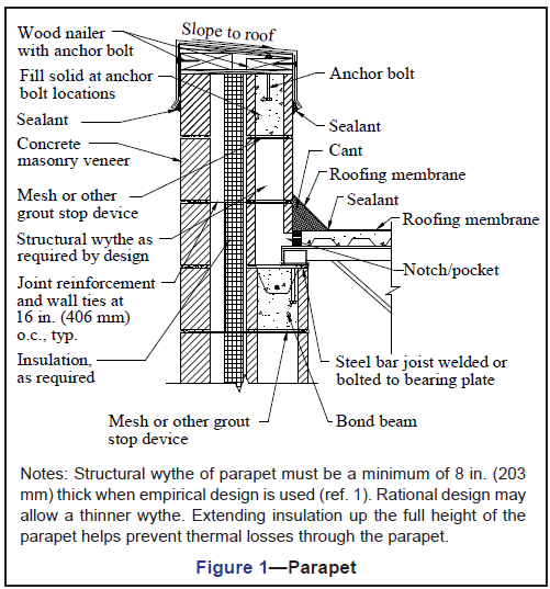
Although veneer crack control measures are similar to those for other concrete masonry wall constructions, specific crack control recommendations have been developed for concrete masonry veneers. These include: locating control joints to achieve a maximum panel length to height ratio of 11/2 and a maximum spacing of 20 ft (6,100 mm), as well as where stress concentrations occur; incorporating joint reinforcement at 16 in. (406 mm) on center; and using Type N mortar for maximum flexibility. See CMU-TEC-009-23, Crack Control Strategies for Concrete Masonry Construction (ref. 2) for more detailed information.
Because the two wythes in a veneer wall are designed to be relatively independent, crack control measures should be employed as required for each wythe. It is generally not necessary for the vertical movement joints in the veneer wythe to exactly align with those in the backup wythe, provided that the ties allow differential in-plane lateral movement.
Wall ties may be joint reinforcement or wire wall ties. Wall ties for veneers transfer lateral loads to the structural wythe and also allow differential inplane movement between wythes. This second feature is particularly important when the two wythes are of materials with different thermal and moisture expansion characteristics (such as concrete masonry and clay brick), or in an insulated cavity wall which tends to have differential thermal movement between the wythes. When horizontal joint reinforcement is used to tie the two wythes together, hot-dipped ladder type reinforcement is preferred over truss type, because the ladder shape accommodates differential in-plane movement and facilitates placing vertical reinforcement, grout and loose fill insulation. Because veneers rely on the backup for support, wall ties must be placed within 12 in. (305 mm) of control joints and wall openings to ensure the free ends of the veneer are adequately supported. More information on ties for veneers can be found in TEK 03-06C, Concrete Masonry Veneers (ref. 4).
The distance between the inside face of the veneer and the outside face of the masonry backup must be a minimum of 1 in. (25 mm) and a maximum of 4 1/2 in. (114 mm). For glazed masonry veneer, because of their impermeable nature, a 2 in. (51 mm) wide airspace is recommended with air vents at the top and bottom of the wall to enhance drainage and help equalize air pressure between the cavity and the exterior of the wall. Vents can also be installed at the top of other masonry veneer walls to provide natural convective air flow within the cavity to facilitate drying. For vented cavities, it is prudent to create baffles in the cavity at the building corners to isolate the cavities from each other. This helps prevent suction being formed in the leeward cavities.
REFERENCES
- Building Code Requirements for Masonry Structures, ACI
530-02/ASCE 5-02/TMS 402-02. Reported by the Masonry
Standards Joint Committee, 2002. - CMU-TEC-009-23, Crack Control Strategies for Concrete
Masonry Construction, Concrete Masonry and Hardscapes
Association, 2023. - TEK 03-06C, Concrete Masonry Veneers, Concrete
Masonry and Hardscapes Association, 2012.